Habicht rifle scopes-Overview Description - OpticsPlanet.com
Habicht rifle scopes-Overview Description - OpticsPlanet.com
Habicht rifle scopes-Overview Description - OpticsPlanet.com

You also want an ePaper? Increase the reach of your titles
YUMPU automatically turns print PDFs into web optimized ePapers that Google loves.
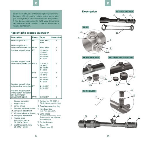
1 Dioptric correction<br />
2 Magnification<br />
3 Screw-on cap<br />
4 Elevation adjustment turret<br />
4.1. Zero point adjustment<br />
5 Windage adjustment turret<br />
5.1. Zero point adjustment<br />
6 Knurled knob<br />
7 Illumination device<br />
BE 3/BE 4 Digital<br />
8 Brightness control ring<br />
BE 3/BE 4 Digital<br />
E<br />
Swarovski Optik, one of the leading European manufacturers<br />
of high-quality optical instruments, wish<br />
you many years of serviceable life with this product.<br />
It has been constructed to fulfill very demanding<br />
requirements and if handled correctly, will remain a<br />
reliable <strong>com</strong>panion.<br />
<strong>Habicht</strong> <strong>rifle</strong> <strong>scopes</strong>-<strong>Overview</strong><br />
<strong>Description</strong> Name Types Image plane<br />
Fixed magnification<br />
Fixed magnification<br />
PF 6x42, 8x50,<br />
8x56<br />
1<br />
with illuminated reticle PF-N 8x50, 8x56 1<br />
Variable magnification<br />
Variable magnification<br />
PV 1.25-4x24<br />
1.5-6x42<br />
2.5-10x42<br />
2.5-10x56<br />
3-12x50<br />
1<br />
with illuminated reticle PVI-2 1.25-4x24<br />
1.5-6x42<br />
2.5-10x56<br />
3-12x50<br />
2<br />
PV-I 1.25-4x24<br />
1.5-6x42<br />
1<br />
Variable magnification<br />
PV-N 2.5-10x42<br />
2,5-10x56<br />
3-12x50<br />
1<br />
with parallax correction PV<br />
Variable magnification<br />
with parallax correction<br />
and quick reticle<br />
4-16x50 P<br />
6-24x50 P<br />
2<br />
adjustment (Sport) PV-S 6-24x50 P 2<br />
24<br />
9Battery for BE 3/BE 4<br />
Digital (button cell CR 2032)<br />
10 Parallax correction ring<br />
11 Hex-head key<br />
(only PV-S 6-24x50 P)<br />
12 Lens shade<br />
(available as accessory for all<br />
42 mm and 50 mm objective<br />
lens diameters)<br />
13 Protective cap<br />
14 Cover SR<br />
(Diagram page 38)<br />
4<br />
4.1.<br />
<strong>Description</strong><br />
PF, PV<br />
11<br />
E<br />
5.1.<br />
9<br />
3 3<br />
8<br />
12 10<br />
7<br />
25<br />
6<br />
5<br />
3 2 1<br />
4<br />
PV, PVI-2, PV-I, PV-N<br />
BE 3 for PF-N, PV-N BE 4 Digital for PVI-2 and PV-I<br />
PV-S 6-24x50 P<br />
13<br />
8<br />
5<br />
7<br />
3<br />
6<br />
9<br />
2 1
For your safety!<br />
WARNING!<br />
E<br />
Never look at the sun with the <strong>rifle</strong><br />
scope! This leads to injury of your<br />
eyes! Please protect your <strong>rifle</strong> scope<br />
from unnecessary solar radiation.<br />
General information<br />
Please protect your <strong>rifle</strong> scope from<br />
jolts and jars.<br />
Repairs should be carried out only<br />
by authorized workshops.<br />
Sealing<br />
Through the use of high-quality sealing elements and controlled<br />
fabrication processes our <strong>rifle</strong> <strong>scopes</strong> are waterand<br />
gas-tight to a pressure of 0.4 bar (corresponds to a<br />
depth in water of 4.4 yds/4 m). Sealing is ensured even<br />
when the screw-on cap has been removed. Exception: <strong>rifle</strong><br />
scope with illuminated reticle without an illumination unit<br />
attached. Nevertheless, careful handling, especially<br />
around the turrets, is advised.<br />
The scope has been filled with nitrogen via the sealing<br />
screw located underneath the windage adjustment<br />
turret. Please do not loosen this sealing screw!<br />
Parallax<br />
a) PF, PF-N, PV, PVI-2, PV-I, PV-N<br />
Your <strong>rifle</strong> scope has been aligned to be parallax free at a<br />
distance of 110 yards (100 meters) (exception: 3-12x50<br />
TDS-Plex at 220 yards [200 meters]). This means that at a<br />
distance of 110 yards (100 meters) the image of the object<br />
aimed at and the image of the reticle are in a single plane.<br />
26<br />
E<br />
Please note that at distances greater or less than 110 yards<br />
(100 meters) minor movements of the reticle image due to<br />
a parallax error can occur as a result of not aligning the<br />
eye with the center of the scope. You can avoid this minor<br />
accuracy problem by careful positioning of the eye.<br />
b) PV 4-16x50 P, PV 6-24x50 P, PV-S 6-24x50 P<br />
With these <strong>scopes</strong> you can set any desired range and therefore<br />
avoid aiming errors due to parallax.<br />
Mounting<br />
Basic alignment<br />
To ensure perfect alignment of the scope to the <strong>rifle</strong>,<br />
please entrust mounting of the scope to a <strong>com</strong>petent<br />
gunsmith.<br />
The reticle has been factory-set to the mechanical<br />
middle position. Prior to mounting you can check the correct<br />
position of the reticle. To do this, unscrew the screwon<br />
caps of the elevation adjustment turret and windage<br />
adjustment turret and turn the respective knurled knob<br />
counter-clockwise until it stops.<br />
a) PF, PV<br />
Now turn the respective knurled knob 1 1 /2 turns clockwise.<br />
b) PV 4-16x50 P, PV 6-24x50 P<br />
• Elevation adjustment<br />
PV 4-16x50 P: turn the knurled knob 3 turns clockwise.<br />
PV 6-24x50 P: turn the knurled knob 4 turns clockwise.<br />
• Windage adjustment<br />
PV 4-16x50 P: turn the knurled knob 1 1 /2 turns clockwise.<br />
PV 6-24x50 P: turn the knurled knob 2 1 /2 turns clockwise.<br />
c) PV-S 6-24x50 P<br />
• Elevation adjustment<br />
Turn the knurled knob 2 turns clockwise.<br />
• Windage adjustment<br />
Turn the knurled knob 1 turn clockwise.<br />
27
E<br />
Alignment of the scope to the <strong>rifle</strong> (“zeroing in”)<br />
If the point of impact of the bullet deviates from the aiming<br />
point, this can be easily and precisely corrected by adjusting<br />
the elevation turret and the windage turret of the scope.<br />
Regardless of corrections, the middle point of the aiming<br />
mark always stays in the middle of the field of view.<br />
a) PF, PV<br />
To make adjustments, simply unscrew the screw-on caps<br />
of the elevation and windage turrets.<br />
b) PV-S 6-24x50 P<br />
To make adjustments here, use the knurled knobs of the<br />
elevation and windage turrets.<br />
When the shot is low<br />
When the shot is high<br />
When the shot is to the left<br />
When the shot is to the right<br />
28<br />
Turn the knurled knob of<br />
the elevation turret in the<br />
direction of H.<br />
Turn the knurled knob of<br />
the elevation turret in the<br />
opposite direction of H.<br />
Turn the knurled knob of<br />
the windage turret in the<br />
direction of R.<br />
Turn the knurled knob of<br />
the windage turret in the<br />
opposite direction of R.<br />
The impact point correction per click can be found in the<br />
technical data or the written information on the elevation<br />
or windage adjustment on your <strong>rifle</strong> scope.<br />
Zero point adjustment<br />
E<br />
Once you have aligned the scope to the <strong>rifle</strong>, you can retain<br />
this setting. The scale for this is located on the respective<br />
knurled knob of the elevation/windage adjustment turret.<br />
a) PF, PF-N, PV, PVI-2, PV-I, PV-N<br />
1. Pull the knurled knob<br />
upwards.<br />
In this position the reticle<br />
spindle is disengaged and<br />
the knurled knob turns<br />
freely.<br />
2. Turn the knurled knob until the zero point of the scale is<br />
aligned with the index point on the scope.<br />
3. Pushing the knurled knob back down re-engages the<br />
reticle spindle and knurled knob. Your individual<br />
setting is now precisely adjusted as the zero point.<br />
b) PV-S 6-24x50 P<br />
1. Use the enclosed hex-head<br />
key to loosen the three<br />
screws on the knurled knob.<br />
The knurled knob can now<br />
be turned freely.<br />
2. Align the zero point of the scale with the index mark and<br />
tighten the three screws to fix the knurled knob in place.<br />
Operation<br />
Carrying out dioptric correction<br />
Your individual setting for optimal focusing of the reticle is<br />
achieved by simply turning the dioptric correction ring.<br />
29
E<br />
First turn the dioptric correction<br />
ring all the way to the left<br />
➀ (counter-clockwise) and<br />
then to the right ➁ until the<br />
reticle is optimally focused.<br />
The adjustment range is 5 dioptres (-3/+2).<br />
Changing magnification<br />
By turning the (stepless) magnification adjustment ring you<br />
can set the desired magnification. The inclined scale allows<br />
simple and easy reading of the setting. For better orientation<br />
the soft, ribbed covering of the adjustment ring has a<br />
nose.<br />
Operation of the illumination units<br />
BE 4 Digital for PVI-2 and PV-I<br />
Please note:<br />
The water and dust tightness of the <strong>rifle</strong> scope can only<br />
be guaranteed with a turret cap or an illumination unit<br />
attached.<br />
1. Mounting the illumination unit<br />
Unscrew the elevation adjustment’s turret cap. The same<br />
thread can now be used to attach the illumination unit. In<br />
order to fully secure the illumination unit use the knurled<br />
part.<br />
30<br />
E<br />
2. Turning on and off<br />
Move the knurled part upwards to turn on the illumination<br />
unit. The red ring “A” be<strong>com</strong>es visible for optical control.<br />
Push the illumination unit down to turn it off.<br />
“A”<br />
3. Brightness modes<br />
The illumination unit has two main brightness modes:<br />
• Daylight mode (16 fine adjustment settings)<br />
• Twilight mode (32 fine adjustment settings)<br />
3.1. Brightness control within a brightness mode<br />
Within a brightness mode (daytime or twilight mode) the<br />
brightness can be adjusted via a sustained pulse as well<br />
as smaller individual pulses.<br />
Sustained pulse<br />
Turn the knurled ring towards the end position in the<br />
desired direction (“+” / “-”) and hold it in this position until<br />
the desired brightness has been achieved.<br />
31
Individual pulses for fine adjustment:<br />
Fine adjustment is possible by using individual pulses.<br />
E<br />
3.2. Switching from daytime to twilight mode<br />
Switching from daytime to twilight mode is achieved with<br />
a sustained pulse of about 2 seconds followed by one<br />
individual pulse.<br />
3.3. Switching from twilight to daytime mode<br />
Switching from twilight to daytime mode is achieved with<br />
a sustained pulse of about 4 seconds followed by one<br />
individual pulse.<br />
4. Storage function<br />
When turning off the illumination unit the last brightness<br />
setting will be stored and activated when the unit is turned<br />
on again.<br />
5. Automatic turn-off function<br />
If, within a period of 3 hours, no brightness adjustment<br />
has been carried out, the illumination unit automatically<br />
turns off.<br />
6. Battery power indicator<br />
If the illuminated reticle begins to flash, this signifies that<br />
a battery change will soon be needed. The remaining<br />
operating time will be a few hours, depending on the<br />
brightness adjustment and ambient temperature.<br />
32<br />
E<br />
7. Changing the battery<br />
• Turn off the illumination unit.<br />
• Hold the knurled ring tightly and unscrew the battery<br />
cover. The use of a coin is advisable for this process.<br />
• Remove the old battery.<br />
• When installing the new battery<br />
(type CR 2032) please<br />
make sure that the side marked<br />
“+” is facing upwards.<br />
•Screw the battery cover back<br />
on.<br />
When disposing of used batteries, please make sure to<br />
<strong>com</strong>ply with local waste and environmental regulations.<br />
Please note!<br />
When the battery is changed the last brightness setting<br />
will be lost. When turning the illumination unit on again it<br />
will be on the maximum brightness setting in the daylight<br />
mode.<br />
8. Battery operating hours<br />
The average operating hours of the battery at medium<br />
brightness are:<br />
• about 38 hours in daytime operation<br />
• about 450 hours in twilight operation.<br />
9. Conformity<br />
The BE 4 illumination unit <strong>com</strong>plies with the Directives of<br />
No. 89/336/EEC regarding electromagnetic <strong>com</strong>patibility.<br />
33
E<br />
BE 3 for PF-N and PV-N<br />
Please note:<br />
The <strong>rifle</strong> scope is properly sealed only when the screwon<br />
cap or the illumination device is screwed on.<br />
a) Mounting the illumination device<br />
Unscrew the screw-on cap of the elevation adjustment turret.<br />
The illumination device BE 3 can be mounted on the<br />
same thread. Use the knurled section of the brightness<br />
control ring to screw on the illumination device snugly.<br />
Please note:<br />
Once the illumination device has been screwed on, it is<br />
switched on!<br />
b) Switching off<br />
Turn the brightness control<br />
ring counter-clockwise past<br />
the clearly audible click until<br />
it stops. Please make sure<br />
that the illumination device is<br />
in the OFF position also after<br />
it has been unscrewed.<br />
c) Brightness control BE 3<br />
On the BE 3 there are two places for variable twilight and<br />
daylight brightness control.<br />
In each case, switching between the two settings takes<br />
place at the end of the turning zone:<br />
Twilight operation<br />
– Turn in clockwise direction until it clicks: dark to light<br />
control<br />
– Fully in clockwise direction: switching from twilight to<br />
daytime operation<br />
<br />
Daytime operation<br />
– Turn in anti-clockwise direction: light to dark control<br />
– Fully in an anti-clockwise direction: “OFF”-position and<br />
switching from daylight to twilight zone.<br />
34<br />
E<br />
d) Changing batteries<br />
• Unscrewing the screw cover.<br />
• Remove the old battery<br />
• When inserting the new battery, make sure that the “+”<br />
side is facing upwards.<br />
• Screw the screw cap back on.<br />
BE 3<br />
Open<br />
Screw-on cap<br />
Button cell<br />
CR 2032<br />
Illumination<br />
device<br />
Usable replacement batteries:<br />
Button cell, 3 V, Type CR 2032<br />
The average operating time of the<br />
battery in medium brightness is about<br />
30 hours in daytime operation and about<br />
400 hours in twilight operation.<br />
When disposing of used batteries, please make sure to<br />
<strong>com</strong>ply with local waste and environmental regulations.<br />
This instrument <strong>com</strong>plies with the Directives of No.<br />
89/336/EEC regarding electromagnetic <strong>com</strong>patibility.<br />
Enclosed replacement battery-box<br />
Unscrew the screw-on cap<br />
of the windage adjustment<br />
turret.<br />
Screw on the enclosed replacement<br />
battery-box.<br />
A spare battery is located in<br />
the replacement battery-box.<br />
35
E<br />
Operation of the <strong>rifle</strong> scope with<br />
parallax adjustment<br />
For shooting disciplines with varying ranges any distance<br />
can be set quickly and precisely right on the objective.<br />
This prevents aiming errors caused by parallax.<br />
a) Adjustment of distance when distance is known<br />
The main ranges are designated<br />
on the conical section of<br />
the parallax correction ring on<br />
the objective between 55 yds/<br />
50 m and infinity. Turn the<br />
parallax correction ring until<br />
the desired range is aligned<br />
with the index point on the<br />
main tube of the scope.<br />
b) Adjustment of distance when distance is unknown<br />
Adjust the magnification to 24x and turn the parallax correction<br />
ring to the right or left until the image in the field<br />
appears to be optimally focused. Now move your eye back<br />
and forth in the area of the exit pupil. If the reticle moves<br />
in relation to the image, correct the range setting until no<br />
difference can be detected between the movement of the<br />
reticle and the movement of the image.<br />
c) Reticle adjustment - PV-S 6-24x50 P<br />
For this, use the knurled knobs of the elevation adjustment<br />
turret and windage adjustment turret.<br />
A one-click adjustment corresponds to 1 /6 MOA (minute of<br />
angle) or a shift of the point of impact of 4.8 mm/100 m<br />
(0.175 in/100 yds).<br />
Table for the conversion of MOA into other angular values<br />
and vice versa.<br />
MOA Degrees ‰ cm/100m in/100yds<br />
1 MOA ^ = 1 0.017 0.29 2.91 1.05<br />
1 Degrees ^ = 60 1 17.45 174.55 62.84<br />
1 ‰ ^ = 3.44 0.057 1 10 3.6<br />
1 cm/100m ^ = 0.34 0.006 0.1 1 0.36<br />
1 in/100yds ^ = 0.95 0.016 0.28 2.78 1<br />
36<br />
The reticle<br />
E<br />
a) in the 1st image plane (objective image plane) on the<br />
PF, PF-N, PV (exceptions see b), PV-N, PV-I:<br />
If the magnification increases then the magnification of<br />
both the image and the reticle is increased, which makes<br />
it easier to estimate the distance to the target.<br />
b) in the 2nd image plane (ocular image plane) on the<br />
PVI-2, PV 4-16x50 P, PV 6-24x50 P and PV-S 6-24x50 P:<br />
If the magnification increases then the reticle remains the<br />
same size – the size of the image is increased, but not the<br />
size of the reticle. Even for large magnifications only a<br />
little of the target is covered.<br />
1 st Image plane:<br />
Image and reticle<br />
are both magnified<br />
to the same extent.<br />
2 nd Image plane:<br />
The image is<br />
magnified, the<br />
reticle remains<br />
unchanged.<br />
37
Standard equipment<br />
E<br />
• The protective caps keep dirt away from the eyepiece<br />
and objective lenses.<br />
• Sunshade for PV 4-16x50 P, PV 6-24x50 P and<br />
PV-S 6-24x50 P.<br />
• Illumination unit and replacement battery-box (battery<br />
included) for PF-N, PVI-2, PV-I and PV-N.<br />
• Swarovski Optik Rail cover:<br />
Maintenance and care<br />
Lens-cleaning cloth<br />
Flexible dust cover is provided<br />
to protect the rail slot and give<br />
a finished appearance, it can<br />
be cut to fit and pressed in by<br />
hand.<br />
You can clean high sensitive lens surfaces with the enclosed<br />
special cloth made of micro-fibres. It is suitable for<br />
objective lens, ocular lens and eye-glasses.<br />
Please keep the cloth clean, as dirt can damage the lens<br />
surface. If the cloth gets dirty, it can be washed in lukewarm<br />
soapy water and air-dried. Please use it exclusively<br />
for cleaning lens surfaces!<br />
Cleaning<br />
We have designed all elements and surfaces to require<br />
little care. To ensure the long-lasting optical brilliance of<br />
your <strong>rifle</strong> scope, you should keep the glass surfaces free<br />
of dirt, oil and grease. When cleaning the lenses, first<br />
remove larger particles with an optical lens brush. For the<br />
subsequent thorough cleaning we re<strong>com</strong>mend breathing<br />
onto the lens surface to form a coat of condensation and<br />
then cleaning it with a soft, moist cloth.<br />
The metal parts can be cleaned best with a soft and<br />
clean cloth.<br />
38<br />
Storage<br />
E<br />
You should keep your <strong>rifle</strong> scope in a well-ventilated and<br />
dry place.<br />
If the instrument is wet, it must be dried prior to storage.<br />
Patents<br />
Denomination Patent numbers<br />
1. Reflex reducing coating:<br />
Swarotop ® US 43 72 987 DE 30 09 533<br />
2. Swarovski coil spring system<br />
for PF and PV <strong>rifle</strong> <strong>scopes</strong> US 54 63 495 EP 654 650<br />
3. Zero setting system for<br />
PF, PV and AV <strong>rifle</strong> <strong>scopes</strong> US 55 13 440 EP 656 519<br />
4. Illuminated reticle for<br />
PF-N and PV-N <strong>rifle</strong> <strong>scopes</strong> US 57 15 607 EP 755 500<br />
5. Illumination device BE 3 DE 10136278<br />
6. Illumination for US; Patent<br />
PVI-2 HIGH GRID EU pat.pend. registered<br />
39
Technical data<br />
E<br />
Functional temperature range: -4 °F/+131 °F (-20 °C/+55 °C) · Storage temperature:<br />
-22 °F/+158 °F (-30 °C/+70 °C) · Sealing: 5.8 lb/sq.in (0.4 bar), filled with nitrogen<br />
Parallax-free at 110 yds/100 m (except PV 3-12x50 TDS-Plex at 220 yds/200 m)<br />
(PV 4-16x50 P, PV 6-24x50 P, PV-S 6-24x50 P: ∞ - 50 m/55 yds)<br />
PF / PF-N PV-S PV / PVI-2 / PV-I / PV-N<br />
Model 6x42 8x50 8x56 6-24x50 P 1.25-4x24 1.5-6x42 2.5-10x42 2.5-10x56 3-12x50 4-16x50 P 6-24x50 P<br />
Magnification 6x 8x 8x 6-24x 1.25x4x 1.5-6x 2.5-10x 2.5-10x 3-12x 4-16x 6-24x<br />
Effective objective Ø 1.65 1.97 2.20 1.97 0.61-0.95 0.77-1.65 1.29-1.65 1.3-2.20 1.55-1.97 1.97 1.97<br />
in (mm) 42 50 56 50 16-24 20-42 33-42 33-56 39-50 50 50<br />
Exit pupil Ø in (mm)<br />
0.28<br />
7<br />
0.25<br />
6.25<br />
0.28<br />
7<br />
0.33-0.08<br />
8.3-2.1<br />
0.49-0.24<br />
12.5-6<br />
0.52-0.28<br />
13.1-7<br />
0.52-0.17<br />
13.1-4.2<br />
0.52-0.22<br />
13.1-5.6<br />
0.52-0.17<br />
13.1-4.2<br />
0.49-0.12<br />
12.5-3.1<br />
0.33-0.08<br />
8.3-2.1<br />
Exit pupil distance 3.15 3.15 3.15 3.15 3.15 3.15 3.15 3.15 3.15 3.15 3.15<br />
in (mm) 80 80 80 80 80 80 80 80 80 80 80<br />
Exit pupil distance – – – – 3.54 3.54 – 3.54 3.54 – –<br />
PVI-2 in (mm) – – – – 90 90 – 90 90 – –<br />
Field of view, real 21 15.6 15.6 18.6-5.4 98.4-31.2 65.4-21 39.6-12.6 39.6-12.3 33-10.5 27.3-7.8 18.6-5.4<br />
ft/100 yds (m/100 m) 7 5.2 5.2 6.2-1.8 32.8-10.4 22.2-7 13.2-4.2 13.2-4.1 11-3.5 9.1-2.6 6.2-1.8<br />
Field of view, real (degrees)<br />
Field of view, apparent<br />
4 3 3 3.5-1 18.6-6 12.4-4 7.5-2.4 7.5-2.4 6.3-2 5.2-1.5 3.5-1<br />
(degrees) 23.2 23.2 23.2 23.2 23.2 23.2 23.2 23.2 23.2 23.2 23.2<br />
Dioptric correction (dpt) +2, -3 +2, -3 +2, -3 +2, -3 +2, -3 +2, -3 +2, -3 +2, -3 +2, -3 +2, -3 +2, -3<br />
Transmission (%)<br />
Twilight performance<br />
94 94/92 93/91 90 93/91 93/91 94/92 93/91 94/92 90 90<br />
Factor (DIN 58388) 16 20 21 17-35 4-10 4-16 7-21 7-24 9-25 11-28 17-35<br />
Correction of point 0.36 0.36 0.36 0.17 0.54 0.36 0.36 0.36 0.36 0.18 0.17<br />
of impact per click 10 10 10 4,8 15 10 10 10 10 5 5<br />
in/100 yds (mm/100 m) ( 1 /6 MOA)<br />
Max. elevation/windage<br />
adjustment range<br />
ft/100 yds (m/100 m)<br />
3.9<br />
1.3<br />
3.3<br />
1.1<br />
3.9<br />
1.3<br />
E: 3.6/W: 2.1<br />
E: 1.2/W: 0.7<br />
9.9<br />
3.3<br />
6.6<br />
2.2<br />
3.9<br />
1.3<br />
3.9<br />
1.3<br />
3.3<br />
1.1<br />
E: 5.4/W: 3 E: 3.6/W: 2.1<br />
E: 1.8/W: 1 E: 1.2/W: 0.7<br />
Length in (mm)<br />
Weight approx. L oz (g)<br />
Main tube:<br />
L: Light alloy<br />
SR: Light alloy with Swarovski Optik Rail<br />
All data are typical values.<br />
SR oz (g)<br />
12.83 13.03 13.27 15.43 11.4 12.99 13.23 13.62 13.4 14.21 15.43<br />
326 331 337 392 290 330 336 346 340 361 392<br />
12.0 13.9 15.9 24.5 13.4 15.7 15.2 18.4 16.9 22.2 23.6<br />
340 395 450 695 380 445 430 520 480 630 670<br />
– – 16.4 – 14.1 16.4 – 19.0 17.5 – –<br />
– – 465 – 400 465 – 540 495 – –<br />
We reserve the right to make changes regarding design and delivery. BA-645/7, 07/2005<br />
40<br />
BE 4 Digital for daylight, BE 3 for daylight,<br />
twilight reticle twilight reticle<br />
Height (in/mm) 0.98 / 25 1.1 / 28<br />
Ø (in/mm) 1.24 / 31.5 1.14 / 29<br />
Weight (oz/g) 1.05 / 30 0.99 / 28<br />
Battery 3V, CR 2032 3V, CR 2032<br />
Average operating Twilight operation at Twilight<br />
period approx. (h) medium brightness: 450 operation: 400<br />
Daylight operation at Daylight<br />
medium brightness: 38 operation: 30<br />
Sealing (assembled) 0.4 bar 0.4 bar<br />
E<br />
41
Dimensions<br />
E<br />
42<br />
PF / PF-N PV-S PV / PVI-2 / PV-I / PV-N<br />
Model 6x42 8x50 8x56 6-24x50 P 1.25-4x24 1.5-6x42 2.5-10x42 2.5-10x56 3-12x50 4-16x50 P 6-24x50 P<br />
A 12.83/326 13.03/331 13.27/337 15.43/392 11.42/290 12.99/330 13.23/336 13.62/346 13.39/340 14.21/361 15.43/392<br />
B 3.15/80 3.15/80 3.15/80 3.15/80 3.15/80 3.15/80 3.15/80 3.15/80 3.15/80 3.15/80 3.15/80<br />
B: PVI-2 – – – – 3.54/90 3.54/90 – 3.54/90 3.54/90 – –<br />
C 6.54/166 6.69/170 6.89/175 8.35/212 4.61/117 6.30/160 6.54/166 6.89/175 6.69/170 7.09/180 8.35/212<br />
D 1.77/45 1.73/44 1.46/37 2.60/66 – 1.93/49 2.09/53 1.46/37 1.73/44 2.60/66 2.60/66<br />
E 3.50/89 3.74/95 3.90/99 4.57/116 0.39/10 3.31/84 3.50/89 3.86/98 3.74/95 4.57/116 4.57/116<br />
F 6.02/153 6.14/156 6.22/158 7.13/181 7.36/187 6.14/156 6.02/153 6.02/153 5.94/151 5.91/150 7.13/181<br />
G 1.10/28 1.10/28 1.10/28 1.10/28 1.10/28 1.10/28 1.10/28 1.10/28 1.10/28 1.10/28 1.10/28<br />
H (only SR) – – 0.63/16 – – 0.63/16 – 0.63/16 0.63/16 – –<br />
I 1.89/48 2.20/56 2.44/62 2.28/58 1.18/30 1.89/48 1.89/48 2.44/62 2.20/56 2.28/58 2.28/58<br />
K 1.00/25,4 1.18/30 1.18/30 1.18/30 1.18/30 1.18/30 1.18/30 1.18/30 1.18/30 1.18/30 1.18/30<br />
L (only SR) – – 0.79/20 – 0.81/20.5 0.79/20 – 0.79/20 0.79/20 – –<br />
M 1.02/26 1.10/28 1.10/28 1.93/49 1.10/28 1.10/28 1.10/28 1.10/28 1.10/28 1.10/28 1.10/28<br />
N<br />
Objective<br />
1.69/43 1.69/43 1.69/43 1.77/45 1.77/45 1.77/45 1.77/45 1.77/45 1.77/45 1.77/45 1.77/45<br />
filter thread M44x0.75 M52x0.75 M58x0.75 M55x0.75 M27x0.75 M44x0.75 M44x0.75 M58x0.75 M52x0.75 M55x0.75 M55x0.75<br />
Dimensions in in/mm<br />
Reticles<br />
PF / PV / PV-S<br />
4 4A<br />
7A<br />
Dot<br />
Plex Crosshair<br />
TDS-Plex<br />
TDS-4<br />
B: PVI-2<br />
PF-N / PV-N<br />
PVI-2 / PV-I<br />
➝<br />
E<br />
4-N 4A-N Plex-N 4-NK<br />
HIGH GRID 4A-IK<br />
4-I<br />
➝<br />
43<br />
➝<br />
HIGH GRID Circle Dot<br />
NEW! NEW! NEW!<br />
LD<br />
HIGH GRID Dot<br />
BD<br />
➝
Subtension dimensions of the reticles<br />
E<br />
The subtension dimensions listed below are based on a<br />
distance of 100 m (resp. 100 yds). For all other distances<br />
the values have to be converted proportionally, e.g. 70 cm/<br />
100 m (resp. 25 in/100 yds) converts into: 140 cm/200 m<br />
(50 in/200 yds); 210 cm/300 m (75 in/300 yds)<br />
* more target coverage see Reticle description<br />
Reticle Models<br />
Subtension dimensions in in/100 yds / cm/100 m<br />
Crosshair Post Horizontal Vertical<br />
Dot<br />
or<br />
opening opening cross<br />
6x42 0.32/0.9 3.24/9 25/70 12.5/35<br />
8x50 0.32/0.9 3.24/9 25/70 12.5/35<br />
8x56 0.40/1.1 4.00/11 25/70 12.5/35<br />
1.25-4x24 0.97/2.7 9.7/27 25/70 12.5/35<br />
4<br />
1.5-6x42 0.65/1.8 6.48/18 25/70 12.5/35<br />
2.5-10x42 0.40/1.1 4.00/11 25/70 12.5/35<br />
2.5-10x56 0.40/1.1 4.00/11 25/70 12.5/35<br />
3-12x50 0.32/0.9 3.24/9 25/70 12.5/35<br />
6x42 0.54/1.5 5.4/15 50/140 25/70<br />
8x50 0.54/1.5 5.4/15 50/140 25/70<br />
8x56 0.54/1.5 5.4/15 50/140 25/70<br />
1.25-4x24 0.97/2.7 9.7/27 50/140 25/70<br />
1.5-6x42 0.65/1.8 6.48/18 50/140 25/70<br />
4A<br />
2.5-10x42 0.54/1.5 5.4/15 50/140 25/70<br />
2.5-10x56 0.54/1.5 5.4/15 50/140 25/70<br />
3-12x50 0.54/1.5 5.4/15 50/140 25/70<br />
4-16x50 P 4x 0.8/2.2 4x 8/22 4x 75.6/210 4x 37.8/105<br />
16x 0.22/0.6 16x 2.2/6 16x 18.7/52 16x 9.4/26<br />
6-24x50 P 6x 0.54/1.5 6x 5.4/15 6x 50/140 6x 25/70<br />
24x 0.14/0.4 24x 1.44/4 24x 12.5/35 24x 6.5/18<br />
7A 1.5-6x42 0.65/1.8 6.48/18 50/140 50/140<br />
2.5-10x42 0.54/1.5 2.16/6 25/70 25/70 –<br />
4-16x50 P 4x 0.3/0.8 4x 1.15/3.2 4x 21.6/60 4x 21.6/60 –<br />
Plex 16x 0.07/0.2 16x 0.3/0.8 16x 5.4/15 16x 5.4/15 –<br />
6-24x50 P 6x 0.21/0.5 6x 0.84/2 26x 15.7/40 26x 15.7/40 –<br />
Crosshair<br />
Dot<br />
24x 0.05/0.1 24x 0.21/0.5 24x 3.9/10 24x 3.9/10 –<br />
PV-S 6x 0.21/0.5 – – – –<br />
6-24x50 P 24x 0.05/0.1 – – – –<br />
PV-S 6x 0.17/0.4 – – – 2 6x Ø 0.84/2,0<br />
6-24x50 P 24x 0.04/0.1 – – – 24x Ø 0.21/0.5<br />
TDS-Plex* 3-12x50 0.6/1.7 5.40/15 50.4/140 50.4/140<br />
TDS-4*<br />
4-16x50 16x 0.18/0.5 16x 0.9/2.5 16x 25.2/70 16x 12.6/35<br />
6-24x50 24x 0.18/0.5 24x 0.9/2.5 24x 25.2/70 24x 12.6/35<br />
44<br />
E<br />
Reticle Models<br />
Subtension dimensions in in/100 yds / cm/100 m<br />
Crosshair Post Horizontal Vertical<br />
Dot<br />
or<br />
opening opening cross<br />
8x50 0.54/1.5 5.40/15 25/70 12.5/35 Ø 0.86/2.4<br />
8x56 0.54/1.5 5.40/15 25/70 12.5/35 Ø 1/2.9<br />
4-N 2.5-10x42 0.54/1.5 5.40/15 25/70 12.5/35 Ø 1/2.9<br />
2.5-10x56 0.54/1.5 5.40/15 25/70 12.5/35 Ø 1/2.9<br />
3-12x50 0.54/1.5 5.40/15 25/70 12.5/35 Ø 0.86/2.4<br />
8x50 0.36/1.0 3.60/10 50.4/140 25.2/70 Ø 0.86/2.4<br />
8x56 0.36/1.0 3.60/10 50.4/140 25.2/70 Ø 1/2.9<br />
4A-N 2.5-10x42 0.36/1.0 3.60/10 50.4/140 25.2/70 Ø 1/2.9<br />
2.5-10x56 0.36/1.0 3.60/10 50.4/140 25.2/70 Ø 1/2.9<br />
3-12x50 0.36/1.0 3.60/10 50.4/140 25.2/70 Ø 0.86/2.4<br />
2.5-10x42 0.54/1.5 5.40/15 25/70 12.5/35 3.6x3.6/10x10<br />
4-NK 2.5-10x56 0.54/1.5 5.40/15 25/70 12.5/35 3.6x3.6/10x10<br />
3-12x50 0.54/1.5 5.40/15 25/70 12.5/35 3.6x3.6/10x10<br />
Plex-N 3-12x50 0.54/1.5 2.16/6 25/70 25/70 –<br />
PVI-2<br />
1.25-4x24<br />
0.86-0.25<br />
2.4-0.7<br />
8.64-2.7<br />
24-7.5<br />
50.76-15.84<br />
141-44<br />
25.34-7.92<br />
70.4-22<br />
Ø 7.2-2.23<br />
Ø 20-6.2<br />
HIGH GRID<br />
4-I<br />
PVI-2<br />
1.5-6x42<br />
PVI-2<br />
2.5-10x56<br />
0.72-0.18<br />
2-0.5<br />
0.43-0.11<br />
1.2-0.3<br />
7.20-1.80<br />
20-5<br />
4.32-1.08<br />
12-3<br />
42.12-10.44<br />
117-29<br />
25.2-6.3<br />
70-17.5<br />
21.24-5.4<br />
59-15<br />
12.6-3.13<br />
35-8.7<br />
Ø 6.01-1.51<br />
Ø 16.7-4.2<br />
Ø 3.6-0.9<br />
Ø 10-2.5<br />
PVI-2<br />
3-12x50<br />
0.36-0.07<br />
1.0-0.2<br />
3.60-0.9<br />
10-2.5<br />
21.24-5.4<br />
59-15<br />
10.44-2.63<br />
29-7.3<br />
Ø 2.99-0.76<br />
Ø 8.3-2.1<br />
PVI-2<br />
1.25-4x24<br />
1.15-0.36<br />
3.2-1.0<br />
8.64-2.7<br />
24-7.5<br />
17.28-5.4<br />
48-15<br />
8.64-2.7<br />
24-7.5<br />
Ø 7.2-2.23<br />
Ø 20-6.2<br />
HIGH GRID<br />
BD<br />
PVI-2<br />
1.5-6x42<br />
0.97-0.25<br />
2.7-0.7<br />
7.20-1.80<br />
20-5<br />
14.4-3.6<br />
40-10<br />
7.2-1.8<br />
20-5<br />
Ø 6.01-1.51<br />
Ø 16.7-4.2<br />
PVI-2<br />
2.5-10x56<br />
0.58-0.14<br />
1.6-0.4<br />
3.60-1.08<br />
12-3<br />
8.64-2.16<br />
24-6<br />
3.6-1.08<br />
12-3<br />
Ø 3.6-0.9<br />
Ø 10-2.5<br />
PVI-2<br />
1.25-4x24<br />
1.37-0.43<br />
3.8-1.2<br />
13.82-4.32<br />
38.4-12<br />
radius of circle<br />
92.16-28.8<br />
256-80<br />
thickness of circle<br />
3.46-1.08<br />
9.6-3<br />
7.2-2.23<br />
20-6.2<br />
HIGH GRID<br />
Circle Dot<br />
PVI-2<br />
1.5-6x42<br />
PV-I<br />
1.25-4x24<br />
1.15-0.29<br />
3.2-0.8<br />
0.7<br />
2<br />
11.52-2.88<br />
32-8<br />
7.1<br />
20<br />
76.68-19.08<br />
213-53<br />
64.8<br />
180<br />
2.88-0.72<br />
8-2<br />
3.1<br />
8.5<br />
5.98-1.51<br />
16.6-4.2<br />
Ø 3.6<br />
Ø 10<br />
PV-I<br />
1.5-6x42<br />
0.7<br />
2<br />
7.1<br />
20<br />
43.2<br />
120<br />
3.0<br />
8.3<br />
Ø 2.38<br />
Ø 6.6<br />
HIGH GRID<br />
PV-I<br />
1.25-4x24<br />
2.5<br />
7<br />
–<br />
–<br />
75.6<br />
210<br />
37.8<br />
105<br />
Ø 7.9<br />
Ø 22<br />
Dot PV-I<br />
1.5-6x42<br />
1.8<br />
5<br />
–<br />
–<br />
50<br />
140<br />
25<br />
70<br />
Ø 5.4<br />
Ø 15<br />
HIGH GRID<br />
4A-IK<br />
PV-I<br />
1.5-6x42<br />
0.54<br />
1.5<br />
5.4<br />
15<br />
50<br />
140<br />
25<br />
70<br />
5.4x5.4<br />
15x15<br />
Horizontal Vertical Length of the vert. horiz./vert.<br />
cross hair cross hair cross hair opening<br />
PVI-2 1.73-0.54 2.30-0.72 57.60-18 13.82-4.32 Ø 7.2-2.23<br />
1.25-4x24 4.8-1.5 6.4-2.0 160-50 38.4-12 Ø 20-6.2<br />
PVI-2 1.44-0.36 1.91-0.47 47.88-11.88 11.52-2.88 Ø 6.01-1.51<br />
HIGH GRID 1.5-6x42 4.0-1.0 5.3-1.3 133-33 32-8 Ø 16.7-4.2<br />
LD<br />
PVI-2 0.86-0.22 1.15-0.29 28.62-7.2 6.84-1.73 Ø 3.6-0.9<br />
2.5-10x56 2.4-0.6 3.2-0.8 79.5-20 19-4.8 Ø 10-2.5<br />
PVI-2 0.72-0.18 0.97-0.25 24.12-6.01 5.76-1.44 Ø 2.99-0.76<br />
3-12x50 2.0-0.5 2.7-0.7 67-16.7 16-4 Ø 8.3-2.1<br />
45