Starr Single Action Army Revolver History
The U.S. Starr Arms Co. produced firearms from 1858 to 1867.Starr double action .44 caliber revolvers, with serial numbers from 1 to about 23,000, were manufactured first in advance of the Civil War and were chosen as one of the three main pistols for the Union forces.
The double action revolvers were complicated and unpopular with Union soldiers. One innovation of that pistol is that what appears to bean ordinary trigger only advances the cylinder. That trigger has to complete its travel to the rear of the trigger guard to trip the small trigger that releases the hammer. The idea was that the revolver would work in double action(cylinder advance and hammer release) but could also work as a sort of single action as the trigger pull advanced the cylinder and cocked the hammer, the second trigger could fire the gun without all the other motion to provide a more sure aim. The effect in Civil War battle however, was more complexity and unreliability so the revolver was unpopular.
The U.S. Ordnance Department persuaded the Starr Arms Co. to create a single-action variant that was simple and more reliable. The hammer was cocked directly and rotated the cylinder and the hammer was then released by the single trigger. Starr single action .44 caliber revolvers were manufactured with serial numbers from about 23,000 to about 54,000.
My revolver with serial number 30500 is close to the middle of this run.
The U.S. Starr Arms Co. ceased operations in 1867 after the Civil War, suggesting that their revolvers were not popular with civilians compared to the competitive revolvers of that time.
The Starr Single Action Army Revolver Serial #30500
Original description of this pistol:
Starr Percussion U.S. Single Action Civil War Army Revolver,.44 caliber with 8 inch barrel. Serial numbered in the 30xxx range and all matching and original. Very good plus with crisp deep grey patina and some salt and pepper. Good bore and working order. Fine grips with good cartouche.
I would add that there was a fair amount of rust in a number of areas and rust immobilized the loading rod latch. There is pitting. The cylinder stop was not functioning properly because the Cylinder Stop part of the Trigger and Cylinder Stop (or “Bolt”) Spring was too short. Finally, the Trigger guard was not matching in serial number although it was most likely original to this pistol.
Starr Single Action Army Revolver (SSAA) Disassembly Notes
I was not able to find disassembly instructions for the Starr Single Action Army Revolver. A schematic of the parts for the modern Pietta model of the Starr Single Action Army Revolver is available. See SSAA Figure 00 Schematic.

Figure 00 Schematic
| 1. | Top Frame | 28. | Loading Lever |
| 2. | Bottom Frame | 29. | Loading Lever Latch |
| 3. | Cylinder | 30. | Loading Lever Latch Spring |
| 4. | Cylinder Hand Locking Pin | 31. | Loading Lever Latch Pin |
| 5. | Cylinder Hand | 32. | Plunger |
| 6. | Trigger Guard | 33. | Trigger Spring Locking Screw |
| 7. | Trigger | 34. | Trigger Guard Screw |
| 8. | Trigger Locking Pin | 35. | Plunger Screw |
| 10. | Backstrap | 36. | Take-down Bolt |
| 11. | Grips | 37. | Mainspring Locking Screw |
| 12. | Hammer | 38. | Cylinder Hand Locking Screw |
| 13. | Hand & Spring | 39. | Hammer/Frames Locking Screw |
| 14. | Hand Spring | 40. | Grip Locking Screw |
| 18. | Mainspring Connecting Rod | 41. | Grip Screw |
| 19. | Mainspring Connecting Rod Pin | 42. | Nipple |
| 20. | Mainspring | 43. | Bolt |
| 25. | Barrel | 44. | Loading Lever Screw |
| 26. | Sight | 45. | Trigger & Bolt Spring |
| 27. | Barrel Catch |
List of 1863 Starr Single Action Revolver Parts
The Starr Single Action Army Revolver Serial #30500 before disassembly. See Figures 01 and 02.

Figure 01

Figure 02
Grip screw removed with a Brownells 240-2 bit (B240-2) bit. Grip removed. See Figure 03.

Figure 03
Take down Bolt unscrewed by hand. Barrel tapped with nylon hammer to open the frame and release the cylinder. See Figure 04.

Figure 04
Barrel/Frame Locking Screw removed with B240-2 bit. See Figure 05.

Figure 05
Grip Locking Screw removed with B240-2 bit and removed Backstrap. See Figure 06.

Figure 06
Loading Lever Screw removed with B240-2 bit See Figure 07.

Figure 07
Note that Barrel is numbered 30500. See Figure 08. Front sight was left in place. Plunger Screw removed with B210-2 bit. See Figure 09.

Figure 08

Figure 09
Loading Lever Latch Pin punched out from the right with a 1.5mm punch. See Figure 10. This releases the Loading Lever Latch and Loading Lever Latch Spring. See Figure 11.
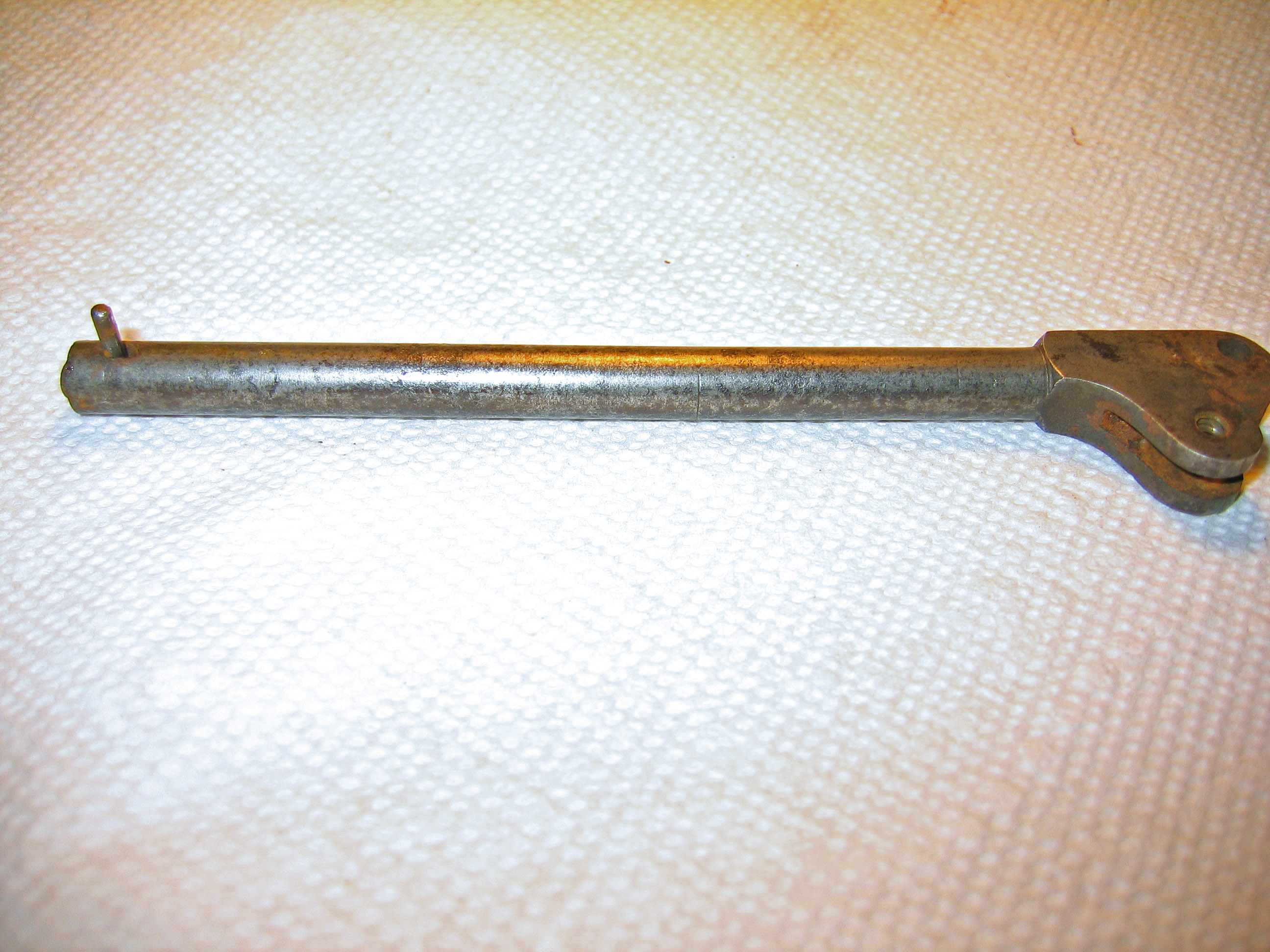
Figure 10

Figure 11
Hammer was placed in full cock and then the Mainspring Locking Screw was removed with B300-3 bit. See Figure 12. Note that there is a shim between the mainspring and the Trigger Guard. See Figure 13. For this particular revolver, the shim is required for the mainspring to have sufficient tension.

Figure 12

Figure 13
Front Trigger Guard Screw removed with a B240-3 bit. See Figure 14.

Figure 14
Rear Trigger Guard Screw removed with a B240-3 bit. See Figure 15.

Figure 15
Trigger Guard removed. See Figure 16.
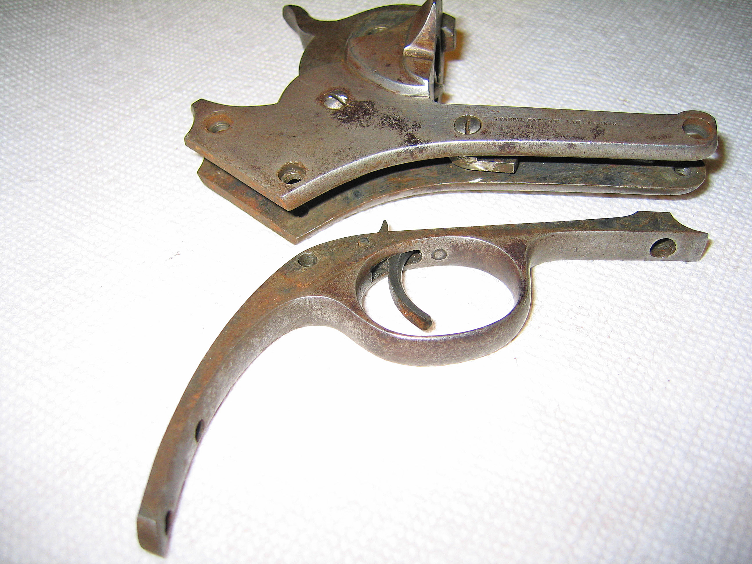
Figure 16
Note that the Trigger Spring Locking Screw, Trigger and Cylinder Stop (or Bolt) Spring and Trigger remain attached to the Trigger Guard and will need to be removed.
Cylinder Stop Screw removed with a B240-3 bit and Cylinder Stop removed from the Frame. See Figure 17.

Figure 17
Note that the Cylinder Stop needs to sit snugly at the right side of the Hammer to be depressed when the Hammer is cocked and it does not appear to be as close to the Hammer as required unless the Cylinder Stop is held in its rectangular opening in the frame by the Trigger and Cylinder Stop Spring. See Figure 18.

Figure 18
Note that the Hammer Screw in this frame is “buggered” and will not turn with a B240-3 bit.
Trigger Spring Screw removed with a B210-2 bit. See Figure 19.
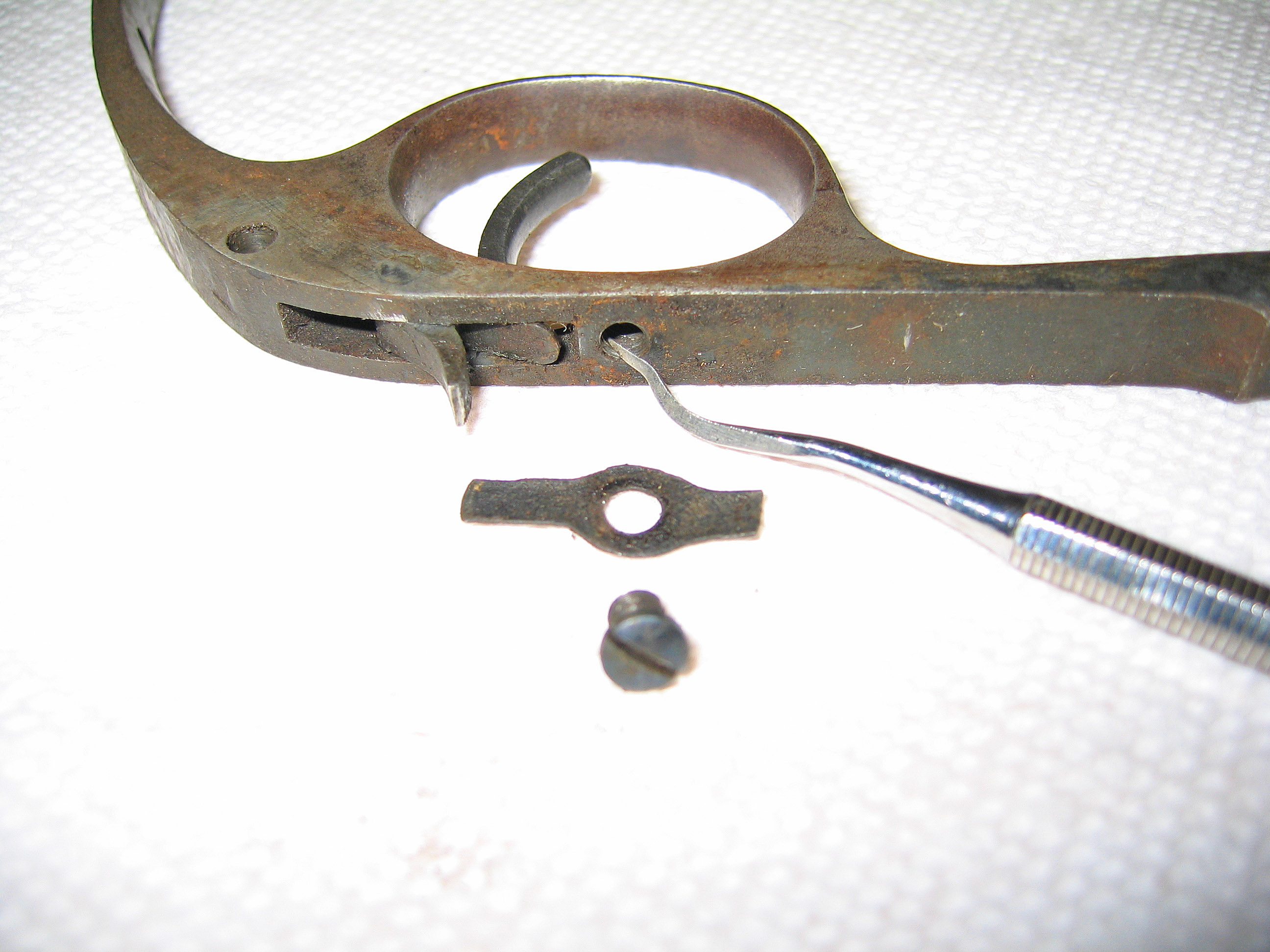
Figure 19
Trigger Pin removed from the right with a 3mm punch. See Figure 20. And Trigger removed from the Trigger Guard. See Figure 21.

Figure 20

Figure 21
Note: Tried to loosen the Hammer Screw with Kroil (a penetrating oil) followed by tapping with a hammer and using a wrench to add torque to the B240-3 bit. The Screw would not move and may be rusted but appears more over-tightened so it probably would only admit of being drilled out to be removed. Plan to leave the Hammer Screw, Hammer and Hand in place in the Frame, See Figure 22 and proceed to clean and apply Renaissance Wax to the SSAA parts.
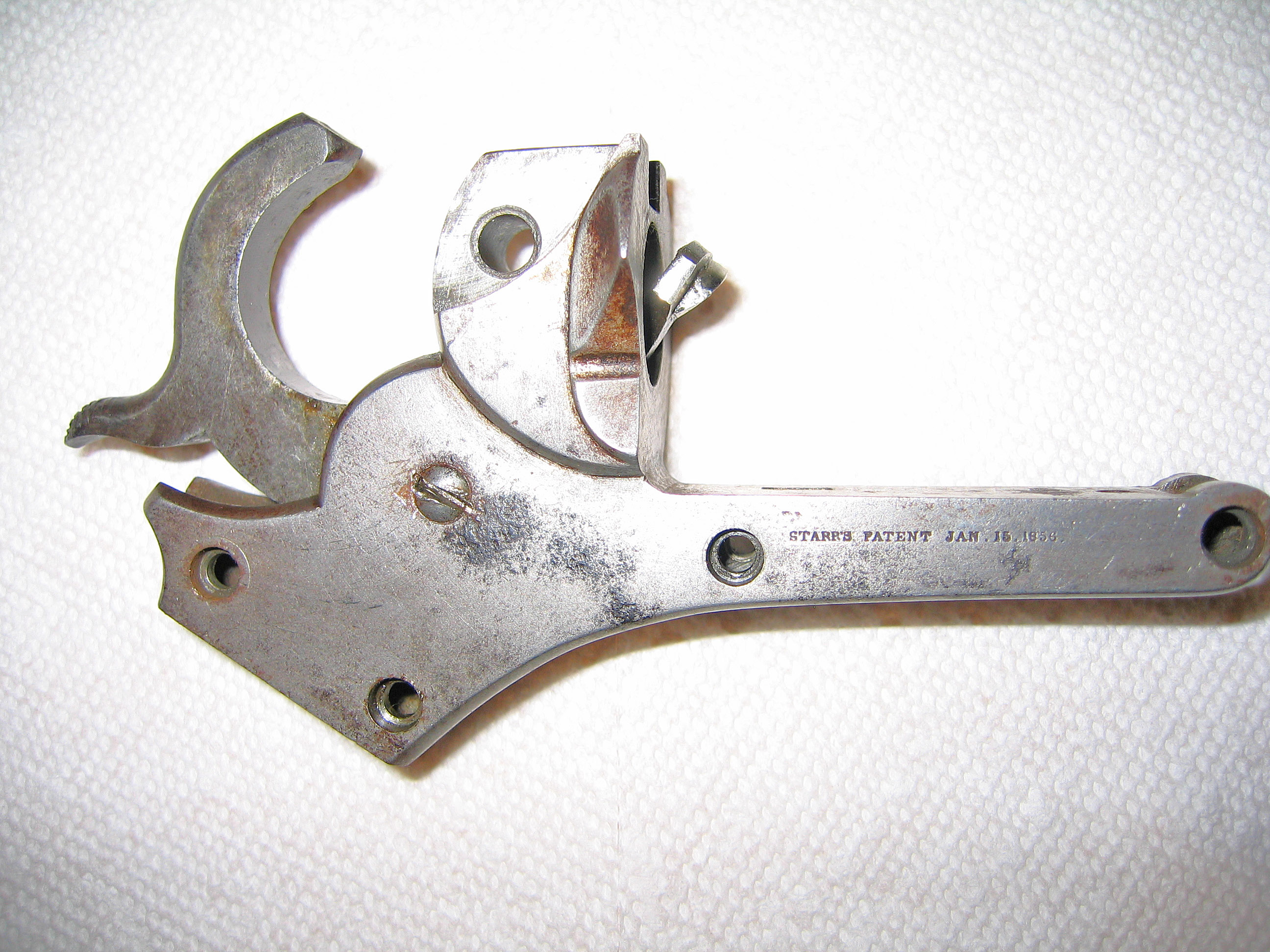
Figure 22
This completes disassembly of the SSAA.
Cleaning:
The Grip was cleaned with Mineral Spirits (MS) and filtered water. Note that this Grip is numbered “30500” on the top cross bar. There is a“2” stamped ¼ inch below the “3” in the serial number.
Grip Screw cleaned with MS and 4-0 Steel Wool (40SW).
The Frame was cleaned with MS and 40SW as well as 600 Wet or Dry Silicon Carbide sandpaper (600SP).
The Barrel and Top Frame Assembly was cleaned with MS, 40SW, 600SP as well as 320 Wet or Dry Silicon Carbide sandpaper (320SP). Note that 320SP and 600SP do not scratch the metal but can remove black pitted rust.
The rest of the parts were cleaned with some combination of MS, 40SW, 600SP and 320SP.
Note that the Trigger Guard is numbered “26194”, not matching. The Backstrap is numbered “80500”, matching.
Applied Renaissance Wax to all parts and buffed lightly with a cotton pad.
SSAA was reassembled in the reverse order of disassembly.
Trigger attached to Trigger Guard with the Trigger Pin inserted from the left and set with a 3mm punch. See Figure 23.

Figure 23
Trigger and Cylinder Stop Spring fixed to Trigger Guard with Trigger Spring Screw using B210-2 bit. See Figure 24.

Figure 24
Cylinder Stop fixed to Frame with Cylinder Stop Screw using B240-3 bit. See Figure 25.

Figure 25
The original Trigger and Cylinder Stop Spring was not able to keep the cylinder stop in place. Replaced the original Trigger and Cylinder Stop Spring with two springs, one for the Trigger and the other for the Cylinder Stop. See Figure 26. This worked, but the Cylinder Stop Spring needed to be stiffer, so both springs were replaced with a single modern replacement for the Trigger and Cylinder Stop Spring. See Figure 27.

Figure 26

Figure 27
The Trigger Guard was fitted to the Frame and Trigger Guard Screws were replaced with a B240-3 bit. See Figure 28.

Figure 28
To reassemble the mainspring, place the hammer in full cock.Attach the mainspring to the mainspring connecting rod attached to the back of the Hammer. Use a clamp or non-marring plier to align the hole in the mainspring with the hole in the Trigger Guard and insert the Mainspring Locking Screw in the hole and begin to tighten the screw. Remove the clamp and tap the Mainspring Shim back in place. Then, fully tighten the Mainspring Locking Screw. See Figure 12 and Figure 29.

Figure 29
Loading Lever Latch and Spring secured with Loading Lever Pin from the left. See Figure 30.

Figure 30
Plunger reattached to Loading Lever and Loading Lever attached to the Barrel See Figure 31.
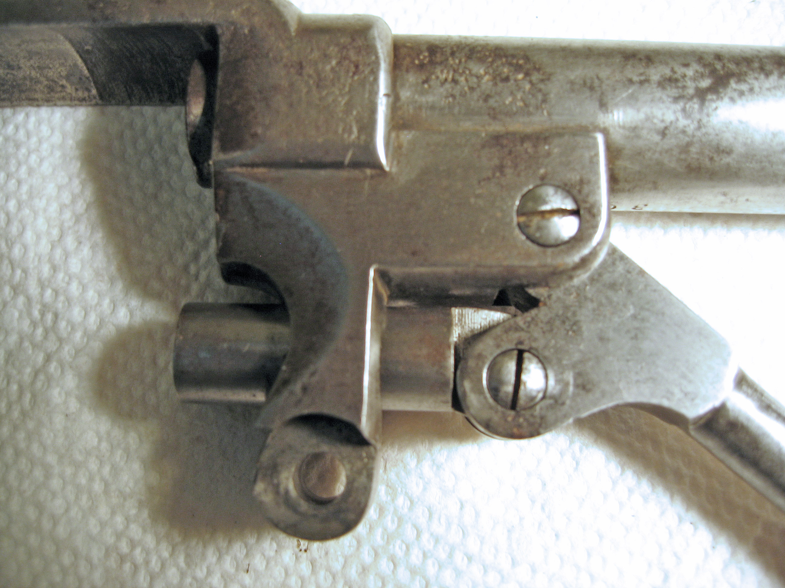
Figure 31
Grip Lock replaced with Grip Locking Screw. See Figure 32.

Figure 32
Barrel and Frame attached with Barrel/Frame Locking Screw See Figure 33.

Figure 33
Take down Bolt replaced and Grip Replaced with Grip Screw.
This completes the reassembly of SSAA.
The Starr Single Action Army Revolver Serial #30500 after disassembly, cleaning and waxing. See Figures 34 and 35.
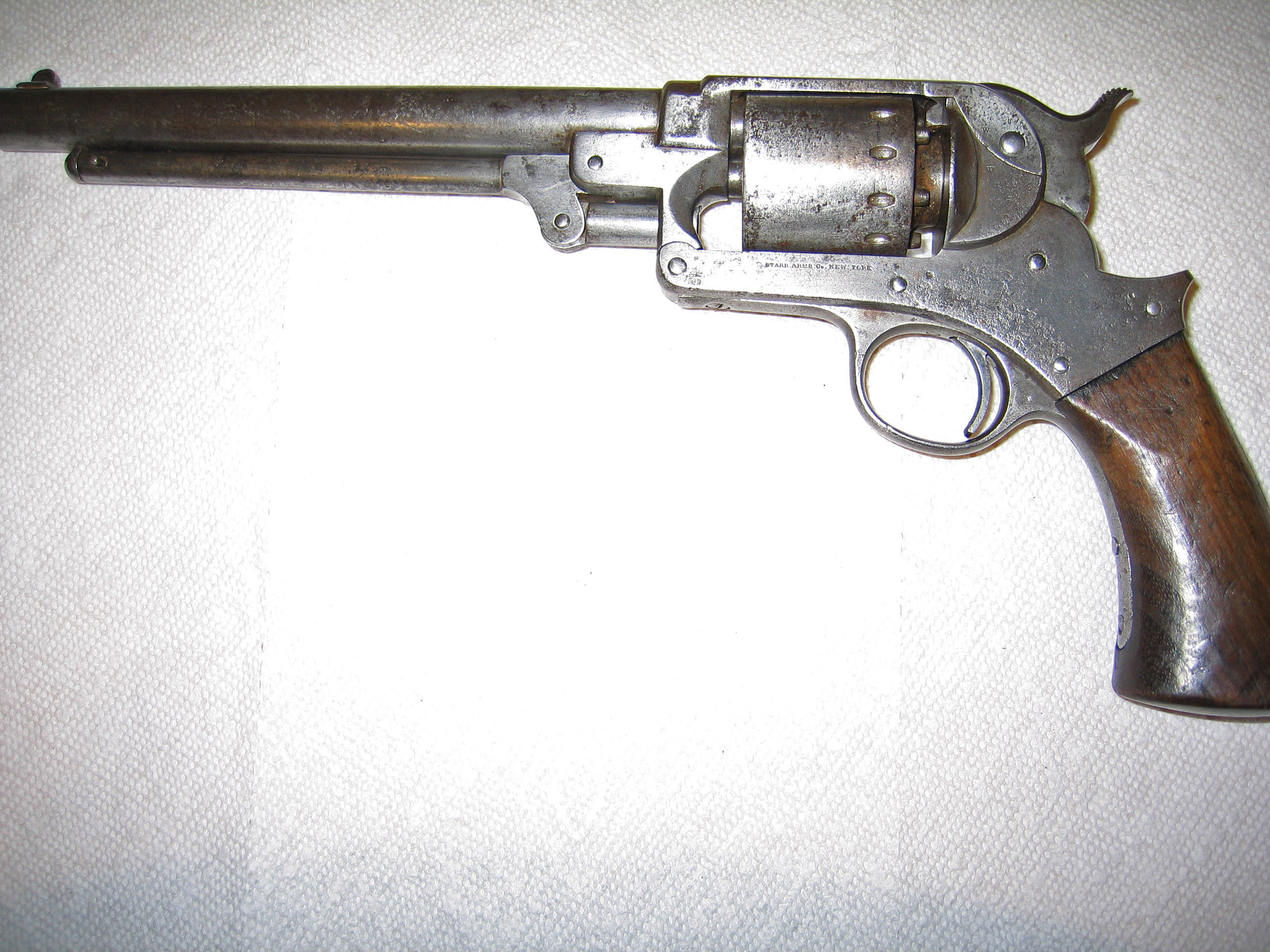
Figure 34

Figure 35

You must be logged in to post a comment.