NVIDIA's SLI: Part 1 - Motherboards
May 16, 2005 | 09:31

DFI LANPARTY nF4 SLI-DR - The Board
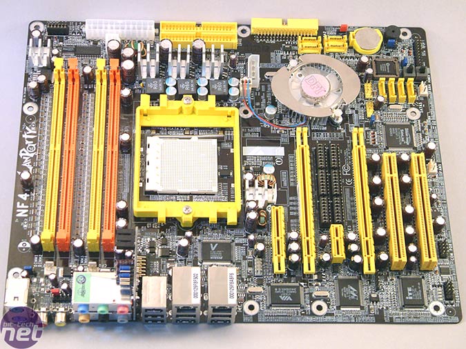 Our initial impressions of the board design are that it is an inspired design that is a little different from the norm - with a very similar layout to MSI's K8N Neo2 Platinum motherboard based on the NForce3 Ultra chipset. Several key components have been moved around that has resulted in more space being created on the motherboard - the most notable part is the CPU, where there seems to be an abundance of space for the larger enthusiast-orientated heatsink designs - although only if you're using one set of the DIMM slots. In between the top PCI-Express x16 slot and the CPU housing, there is a 5/12v floppy-style power connector from the power supply - DFI recommend using this, along with the additional 4-pin molex connector located above the chipset fan for added stability when overclocking the board.
There is a definitive theme to the board, with all plastic pieces on the board being UV reactive falling right in line with the IDE and SATA cables that are included. The memory slots are coloured by channel so you need to install memory modules in the same coloured slots to make use of Dual Channel mode - slot 2 and slot 4 (the orange ports) are recommended by DFI for the best results.
Above the CPU socket, there is the two ATA133 IDE ports, the 4-pin 12v power connector and the 24-pin ATX connector - which supports both 24-pin and 20-pin ATX power supplies. In the top left hand corner of the motherboard, there is the memory voltage jumper - this controls the maximum allowable memory voltage. When the jumper is moved from the default position, it allows selection of memory voltages up to 4.0v. However, in order to access vDIMM values above 3.1v, you must change set the CPU voltage manually, rather than allowing the BIOS to auto select CPU voltage.
The four SATA ports above the chipset fan are controlled by the chipset's Serial-ATA II controller which is fully RAID 0 and 1 compatible allowing you to stripe or mirror an array of hard drives across either two or four ports. Moving to the right of the NForce 4 SLI chipset, there are the four SATA150 ports controlled by the Silicon Image 3114 controller. Next to these, there is the on-board power and reset switches, the BIOS chip and the safe boot jumper that allows you to boot up after pushing the motherboard too far without having to reset the CMOS and thus losing all previous settings.
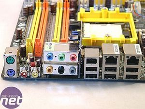
 The I/O back panel features two PS/2 ports, six USB 2.0 ports, the two Gigabit Ethernet ports, an IEEE 1394 port and S/PDIF RCA In/Out ports. The audio module is a separate Karajan audio riser providing six analogue audio ports and a CD-In header too.
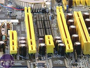
The SLI controller is a little different to the other motherboards on test here - DFI have chosen to use a block of jumpers rather than the switcher card that the other motherboards are using. The design works well, and in all honesty we didn't see much of an problem with switching a few jumpers instead of switching a card. In essence, you are only going to switch between video modes on a rare occasion and possibly only once.
The BIOS
The BIOS is nothing short of a tweakers heaven - there are many, many options for the serious overclocker, making this board one that does not require a great deal of modification in order to achieve the high voltages required for record-breaking overclocks. DFI have used the AwardBIOS with a few board-specific options added to bring extra spice for the enthusiast.
The avid overclocker will be interested in the Genie BIOS page, where the majority of the interesting tweaks can be found including the likes of processor manipulation, memory setup and voltages for just about everything you would want to adjust the voltage on. We've already mentioned that there is support for up to 4.0v of vDIMM depending on the jumper configuration, and there's also the option to supply up to 2.1v vCore to the CPU via a multiplier - this isn't recommended if you have anything short of high-end phase change cooling, and an element of extreme madness supplied with the phase change cooler.
We had issues with some memory modules with early BIOS revisions where it was not selecting the correct timings for the modules, meaning that the board would not boot in dual channel with any Samsung TCCD-based memory modules we tried. Fortunately, we are glad to say that DFI have addressed these issues with several new BIOS revisions being released in order to fix the issues that we were having.
There is a definitive theme to the board, with all plastic pieces on the board being UV reactive falling right in line with the IDE and SATA cables that are included. The memory slots are coloured by channel so you need to install memory modules in the same coloured slots to make use of Dual Channel mode - slot 2 and slot 4 (the orange ports) are recommended by DFI for the best results.
Above the CPU socket, there is the two ATA133 IDE ports, the 4-pin 12v power connector and the 24-pin ATX connector - which supports both 24-pin and 20-pin ATX power supplies. In the top left hand corner of the motherboard, there is the memory voltage jumper - this controls the maximum allowable memory voltage. When the jumper is moved from the default position, it allows selection of memory voltages up to 4.0v. However, in order to access vDIMM values above 3.1v, you must change set the CPU voltage manually, rather than allowing the BIOS to auto select CPU voltage.
The four SATA ports above the chipset fan are controlled by the chipset's Serial-ATA II controller which is fully RAID 0 and 1 compatible allowing you to stripe or mirror an array of hard drives across either two or four ports. Moving to the right of the NForce 4 SLI chipset, there are the four SATA150 ports controlled by the Silicon Image 3114 controller. Next to these, there is the on-board power and reset switches, the BIOS chip and the safe boot jumper that allows you to boot up after pushing the motherboard too far without having to reset the CMOS and thus losing all previous settings.
The SLI controller is a little different to the other motherboards on test here - DFI have chosen to use a block of jumpers rather than the switcher card that the other motherboards are using. The design works well, and in all honesty we didn't see much of an problem with switching a few jumpers instead of switching a card. In essence, you are only going to switch between video modes on a rare occasion and possibly only once.
The BIOS
The BIOS is nothing short of a tweakers heaven - there are many, many options for the serious overclocker, making this board one that does not require a great deal of modification in order to achieve the high voltages required for record-breaking overclocks. DFI have used the AwardBIOS with a few board-specific options added to bring extra spice for the enthusiast.
The avid overclocker will be interested in the Genie BIOS page, where the majority of the interesting tweaks can be found including the likes of processor manipulation, memory setup and voltages for just about everything you would want to adjust the voltage on. We've already mentioned that there is support for up to 4.0v of vDIMM depending on the jumper configuration, and there's also the option to supply up to 2.1v vCore to the CPU via a multiplier - this isn't recommended if you have anything short of high-end phase change cooling, and an element of extreme madness supplied with the phase change cooler.
We had issues with some memory modules with early BIOS revisions where it was not selecting the correct timings for the modules, meaning that the board would not boot in dual channel with any Samsung TCCD-based memory modules we tried. Fortunately, we are glad to say that DFI have addressed these issues with several new BIOS revisions being released in order to fix the issues that we were having.


MSI MPG Velox 100R Chassis Review
October 14 2021 | 15:04


Want to comment? Please log in.