ICM7218
Hello world!!!!
In this page we are going to get some over look on popular
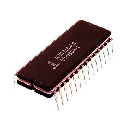
ICM7218A seven segment driver IC from intersil.
Topics we are going explain are as follows:
- How it works?
- Interfacing with micro-controller (atmega16).
- Cascading multiple ICM7218A.
- Embedded C code.
It's 28 pin IC can drive up to 8 seven segments, with two control pin's it controls entire IC. off course other pins also required haa haa any way.
Control Pins- MODE(PIN NO 9), WRITE(PIN 8)
Subcontrol Pins- HEX/CODEB(PIN NO 5), DECODE(PIN 6), DATA COMING( PIN NO 7), SHUTDOWN(PIN NO 10).
NOTE: Subcontrol has dual function it can be data or mention above.
 | |||||||||||||||||||||||
| ICM7218A |
it's working is very simple & as follows:
1. Set mode pin HIGH i.e '1'.
2. Set write pin HIGH i.e '1'.
3. load the control byte on ID4-ID7(load the control byte as per requirment).
Ex. shutdown pin signifies normal or shutdown you can choose either of this, if you want decode mode then use decode pin to do this, then you have to choose either hex or CODEB mode, if you want to send the data after control byte then use pin DATACOMING but if you use this you have to have send the 8 bytes of data after control byte.(we will see this in code).
4.Set write pin LOW i.e '0'.
5.Set write pin HIGH i.e '1'.
That's it we set control byte & now look for data bytes.
it's plain simple just send 8 bytes on ID0- ID7 for sequentially. this data coming should be when writing control byte.(If using no decode mode other wise 4 bits will be sufficient).
CODE
#include
<mega16.h>
#include
<delay.h>
#define Write_Pin 0
#define Write_Pin_Direction 0
#define Mode_Port DDRA
#define Data_Port PORTC
#define Set_Data_Port_Direction DDRC=0XFF
#define no_of_digits 64
#define Count_for_one_display 0
#define Write_Pin_Direction 0
#define Mode_Port DDRA
#define Data_Port PORTC
#define Set_Data_Port_Direction DDRC=0XFF
#define no_of_digits 64
#define Count_for_one_display 0
//unsigned char
display_var[no_of_digits]={0};
unsigned char
Mode_Pin=0;
unsigned char
Segment_code[11]={0x7B,0X30,0X6D,0X75,0X36,0X57,0X5F,0X70,0X7F,0X77};
void
display_init()
{
/*********
PORTC.1 & PORTC.0 is used for mode pin & write pin resp while PORTA is
used for data**********/
Set_Data_Port_Direction;
Mode_Port=0xff;
DDRB|= (1<<Write_Pin_Direction);
}
void
Control_routine(unsigned char Control_byte)
{
PORTA=(1<<Mode_Pin);
PORTB=(1<<Write_Pin) ;
// delay_ms(20);
Data_Port= Control_byte;
// delay_ms(20);
PORTB&=~(1<<Write_Pin);
// delay_ms(20);
PORTB=1<<Write_Pin;
PORTA=0;
}
void
Data_routine(unsigned char Data_byte)
{
PORTB=(1<<Write_Pin) ;
// delay_ms(20);
Data_Port= Data_byte;
// delay_ms(20);
PORTB&=~(1<<Write_Pin);
// delay_ms(20);
PORTB=(1<<Write_Pin) ;
Data_Port=0;
}
void
All_Display_Routine()
{
//
Control data"normal mode , decode ,hex decode & data
coming"
// Control_routine(0XD0);
//
for(count=7;count>=Count_for_one_display;count--)
// {
// if(count==0)
// {
// Data_routine(count);
// }
// else
// {
// Data_routine(count|1<<7);
// }
//
// }
//
delay_ms(1000);
}
void
all_display()
{
unsigned char
count,outer_count;
for(outer_count=0;outer_count<=7;outer_count++)
{
Control_routine(0XF0);
for(count=0;count<=7;count++)
{
Data_routine(0X7B);
}
}
}
void
blink_display()
{
unsigned char count,outer_count;
for(outer_count=0;outer_count<=7;outer_count++)
{
Control_routine(0XF0);
for(count=0;count<=7;count++)
{
if(count<4)
{
Data_routine(1<<7|0);
}
else
{
Data_routine(0X7B);
}
}
}
}
void main()
{
//
delay_ms(1000);
display_init();
All_Display_Routine();
while(1)
{
all_display();
//
delay_ms(500);
blink_display();
// delay_ms(500);
}
}
Code has been tested on hardware. just play with code uncomment/ comment it will understand it.you can connect multiple max 7218 with all pins common between all 7218 & microcontroller except for mode which should be separate for each7218.
thank you for reading !!!!
No comments:
Post a Comment