US9313102B2 - Configuration validation in a mixed node topology - Google Patents
Configuration validation in a mixed node topology Download PDFInfo
- Publication number
- US9313102B2 US9313102B2 US14/094,931 US201314094931A US9313102B2 US 9313102 B2 US9313102 B2 US 9313102B2 US 201314094931 A US201314094931 A US 201314094931A US 9313102 B2 US9313102 B2 US 9313102B2
- Authority
- US
- United States
- Prior art keywords
- nodes
- node
- type
- topology
- link
- Prior art date
- Legal status (The legal status is an assumption and is not a legal conclusion. Google has not performed a legal analysis and makes no representation as to the accuracy of the status listed.)
- Active, expires
Links
Images


Classifications
-
- H—ELECTRICITY
- H04—ELECTRIC COMMUNICATION TECHNIQUE
- H04L—TRANSMISSION OF DIGITAL INFORMATION, e.g. TELEGRAPHIC COMMUNICATION
- H04L41/00—Arrangements for maintenance, administration or management of data switching networks, e.g. of packet switching networks
- H04L41/12—Discovery or management of network topologies
-
- H—ELECTRICITY
- H04—ELECTRIC COMMUNICATION TECHNIQUE
- H04L—TRANSMISSION OF DIGITAL INFORMATION, e.g. TELEGRAPHIC COMMUNICATION
- H04L41/00—Arrangements for maintenance, administration or management of data switching networks, e.g. of packet switching networks
- H04L41/08—Configuration management of networks or network elements
- H04L41/0866—Checking the configuration
- H04L41/0873—Checking configuration conflicts between network elements
-
- H—ELECTRICITY
- H04—ELECTRIC COMMUNICATION TECHNIQUE
- H04L—TRANSMISSION OF DIGITAL INFORMATION, e.g. TELEGRAPHIC COMMUNICATION
- H04L41/00—Arrangements for maintenance, administration or management of data switching networks, e.g. of packet switching networks
- H04L41/08—Configuration management of networks or network elements
- H04L41/0866—Checking the configuration
Definitions
- FIG. 1A illustrates the front face of an exemplary stackable switch 100 according to an embodiment.
- stackable switch 100 includes a set of data ports 102 , a set of stacking ports 104 , and a console port 106 .
- Data ports 102 are operable for connecting stackable switch 100 to one or more hosts and/or data networks.
- Stacking ports 104 are operable for linking stackable switch 100 to other stackable switches in the same stacking system/topology.
- Stacking ports 104 can be dedicated ports (i.e., ports designed specifically for stacking) or high bandwidth data uplink ports that operate in a stacking mode.
- console port 106 is operable for accessing the management console of stackable switch 100 in order to perform various device management functions.
- FIG. 1B illustrates an exemplary stacking system 150 according to an embodiment.
- stacking system 150 comprises a number of stackable switches 152 , 154 , and 156 (each similar to stackable switch 100 of FIG. 1A ) that have been linked together via their respective stacking ports.
- stackable switches 152 , 154 , and 156 form a ring topology.
- stackable switch 154 is designated as the “master” unit of stacking system 150 , which means that switch 154 serves as the point of user contact for all management functions of system 150 .
- stackable switch 154 can accept and process user commands directed to the overall configuration of stacking system 150 .
- Stackable switch 154 can also communicate with non-master units 152 and 156 on an as-needed basis in order to propagate various types of management commands and data to those units.
- prior art stacking systems are limited to relatively simple topologies like the ring topology depicted in FIG. 1B .
- new stacking technologies such as Brocade Communications Systems' “HyperEdge” technology, support more complex topologies (e.g., arbitrary meshes). These complex topologies are beneficial because they can provide better performance (through reduced switch-to-switch latency) and superior resiliency (via redundant stacking paths).
- HyperEdge supports a feature known as “mixed” stacking, which allows high-end stackable switches (i.e., switches with more features, ports, and/or bandwidth) to be combined with low-end stackable switches (i.e., switches with fewer features, ports, and/or bandwidth) in a single stacking system.
- high-end stackable switches i.e., switches with more features, ports, and/or bandwidth
- low-end stackable switches i.e., switches with fewer features, ports, and/or bandwidth
- topology support and mixed stacking have clear benefits for users, they can also complicate stacking system administration and management, particularly in instances where an administrator wishes to make topology configuration changes.
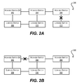
- stacking system 200 depicted in FIGS. 2A and 2B which comprises three high-end switches 202 , 204 , 206 and three low-end switches 208 , 210 , 212 that are interconnected via a mesh-like topology.
- High-end switch 202 is the master unit in this configuration.
- an administrator attempts to remove the stacking link between high-end switch 206 and low-end switch 212 from the system's topology configuration as shown in FIG. 2A .
- the removal of the stacking link will cause low-end switch 212 to be unreachable by the master unit (i.e., high-end switch 202 ), and thus will break the system (since switch 202 can no longer communicate management commands/data to switch 212 ).
- a device can identify a link to be removed from a topology comprising a plurality of nodes, where the plurality of nodes includes one or more nodes of a first type and one or more nodes of a second type. The device can then determine whether the removal of the link from the topology would require data traffic between two nodes of the first type to pass through a node of the second type.
- FIG. 1A depicts a stackable switch according to an embodiment.
- FIG. 1B depicts a stacking system according to an embodiment.
- FIG. 2A depicts a scenario where the removal of a stacking link results in an unreachable unit.
- FIG. 2B depicts a scenario where the removal of a stacking link causes traffic between two high-end units to flow through a low-end unit.
- FIG. 3 depicts a mixed node topology according to an embodiment.
- FIG. 4 depicts an algorithm for validating the removal of a link in a mixed node topology according to an embodiment.
- FIGS. 5A and 5B depict example applications of the algorithm of FIG. 3 .
- FIG. 6 depicts a network switch according to an embodiment.
- a “mixed node topology” refers to a set of interconnected nodes, where the set includes at least two different node types, and where some of the node types are more “capable” than others (e.g., may support greater bandwidth, a larger number of ports, a higher level of security clearance, etc.).
- the set of interconnected nodes includes a master node of the most capable node type.
- a particular node in the topology e.g., the master node
- the master node can receive a user command to remove the link (or a port/trunk associated with the link). The master node can then execute a validation algorithm to ensure that the removal of the link will not cause (1) any node to become unreachable by the master node, and (2) traffic between two nodes to flow through a node that is less capable than either of the two nodes. If the algorithm returns a successful result (indicating that the removal of the link will not cause (1) and/or (2)), the master node can allow the link removal to occur. On the other hand, if the algorithm returns an unsuccessful result (indicating that the removal of the link will cause (1) or (2)), the master node can prevent the link from being removed from the topology.
- the validation algorithm noted above can be particularly useful when applied to stacking systems that use mixed stacking in combination with complex (e.g., mesh-like) topologies.
- the algorithm can avoid the problematic scenarios described with respect to stacking system 200 of FIGS. 2A and 2B .
- embodiments of the present invention are not limited to stacking systems, and may be used to validate link removal in any arbitrary mixed node topology (e.g., general L2/L3 networks or fabrics).
- FIG. 3 depicts an example of a mixed node topology ( 300 ) according to an embodiment.
- topology 300 includes a set of nodes of a first type (i.e., 302 , 304 , 306 , 308 , 310 , 312 ) that are identified by a heavy outline, and a set of nodes of a second type (i.e., 314 , 316 ) that are identified by a lighter outline.
- Node 302 is designated a master node, and thus is responsible for facilitating the configuration and management of topology 300 .
- the nodes of the first type are “high-end” nodes (e.g., high-end stackable switches), while the nodes of the second type are “low-end” nodes (e.g., low-end stackable switches).
- high-end nodes 302 , 304 , 306 , 308 , 310 , 312 have more and/or superior capabilities than low-end nodes 314 , 316 .
- high-end nodes 302 , 304 , 306 , 308 , 310 , 312 can have higher bandwidth communication ports than low-end nodes 314 , 316 .
- high-end nodes 302 , 304 , 306 , 308 , 310 , 312 can have other characteristics that distinguish these nodes from low-end nodes 314 , 316 (e.g., a larger number of ports, more advanced network processing capabilities, a higher level of security clearance, etc.).
- the removal of a link may cause one or more nodes to be inadvertently “severed” from (i.e., rendered unreachable by) master node 302 , thereby preventing master node 302 from communicating management commands and/or data to the severed nodes.
- the removal of a link may cause traffic between two or more high-end nodes (e.g., 302 , 304 , 306 , 308 , 310 , 312 ) to traverse through a low-end node (e.g., 314 , 316 ). Since, in the example of FIG. 3 , the links between high-end nodes and low-end nodes have a lower bandwidth capacity than the links directly interconnecting high-end nodes, this situation can undesirably lead to congestion and reduced system performance.
- master node 302 can execute a validation algorithm at the time a link removal is to occur within topology 300 (e.g., at the time an administrator or other agent submits a “remove link” or “remove port” command).
- the validation algorithm can check whether the removal of the link will result in any unreachable nodes.
- the validation algorithm can check whether the removal of the link will cause traffic between any two nodes to flow though a less capable node. If the algorithm determines that either of these scenarios will occur, master node 302 can block the link removal from proceeding. In this way, the undesirable consequences associated with these scenarios can be automatically avoided, without any manual intervention by a user or administrator.
- this validation algorithm can be applied any arbitrary topology (e.g., ring, linear, mesh, etc.), and is not limited to specific types of topologies. Thus the same algorithm may be used across a variety of different deployments, each having different topological requirements/characteristics.
- topology 300 depicts only two node types for purposes of illustration (i.e., a high-end node type and low-end node type)
- the validation algorithm may be applied to topologies that have more than two different node types (where each node type has a corresponding “capability” level).
- the algorithm can ensure that traffic between any two nodes in the topology (of the same or different node types) will not pass through a node of a less capable type than either of the two nodes.
- FIG. 4 depicts a flowchart 400 that can be performed by master node 302 of FIG. 3 for carrying out the validation algorithm described above according to an embodiment.
- Flowchart 400 assumes that master node 302 has access to the current configuration of topology 300 .
- master node 302 can identify a link to be removed from topology 300 .
- topology 300 is a stacking system
- master node 302 can receive a user command to remove a particular stacking port or trunk from a stackable switch in the system. Master node 302 can then identify the link to be removed based on the specified port/trunk ID.
- master node 302 can create a copy of the current topology configuration and remove the link from the copy. Master node 302 can subsequently enter a loop for each endpoint of the link (block 406 ).
- master node 302 can first create a “node set” and add the current endpoint node as the node set's initial member (block 408 ). Upon creating the node set, master node 302 can enter a second loop for each node set member (block 410 ).
- master node 302 can, for each node directly connected to the current node set member in the copy of the topology configuration, add the node to the node set (block 412 ). If the node is already part of the node set, it is not added again. In a particular embodiment, as part of the processing of block 412 , master node 302 can enforce a restriction where a directly connected node is not added to the node set if the directly connected node is less capable than the current node set member (e.g., the directly connected node is a low-end node and the current node set member is a high-end node). In the context of topology 300 of FIG. 3 , this restriction effectively prevents the algorithm from considering paths through topology 300 that flow from a high-end node though a low-end node and back to a high-end node.
- a directly connected node is not added to the node set if the directly connected node is less capable than the current node set member (e.g., the directly
- master node 302 can check whether the node set now includes itself (i.e., the master node) (block 414 ). In other words, master node 302 can check whether a path has been established from the endpoint node to the master node. If not, the current iteration of loop 410 can end (block 416 ) and master node 302 can repeat loop 410 in order to recursively process additional members in the node set (including new members added at block 412 ).
- master node 302 can conclude that there is no viable path from the endpoint node to the master node and can return a “FAIL” result (indicating that the link removal should not be allowed) (block 418 ).
- master node 302 can check whether the current endpoint node (within loop 406 ) is the last (i.e., second) endpoint node to be processed. If so, master node 302 can conclude there are viable paths between each endpoint node of the removed link and the master node, and can return a “SUCCESS” result (indicating that the link removal should be allowed) (block 424 ). Otherwise, the current iteration of loop 406 can end (block 422 ) and master node 302 can repeat loop 406 in order to process the second endpoint node of the removed link. This second iteration of loop 406 will ultimately result in a “FAIL” result per block 418 or a “SUCCESS” result per block 424 .
- master node 302 can first check whether the link is “live” (i.e., physically connected). Master node 302 can determine this by, e.g., referencing an internal representation of the physical topology, or running a topology discovery algorithm. If the link is not live, master node 302 can return a “SUCCESS” result (i.e., allow the link removal to proceed), without continuing with the rest of the algorithm.
- live i.e., physically connected
- master node 302 can return a “SUCCESS” result (i.e., allow the link removal to proceed), without continuing with the rest of the algorithm.
- each endpoint node of the removed link can perform a slightly modified version of blocks 408 - 424 that returns either a “SUCCESS” result (if the master node is added to the node set for the endpoint node) or a “FAIL” result (if the master node is never added to the node set for the endpoint node).
- Each endpoint node can then transmit its result to master node 302 , which can allow the link removal if both endpoint nodes return “SUCCESS” or block the link removal if either endpoint node returns “FAIL.”
- master node 302 can allow the link removal if both endpoint nodes return “SUCCESS” or block the link removal if either endpoint node returns “FAIL.”
- FIGS. 5A and 5B depict exemplary scenarios 500 and 550 where the algorithm is used to validate the removal of certain links in topology 300 of FIG. 3 .
- the link to be removed is link 326 (between high-end nodes 306 and 310 ).
- the algorithm first processes endpoint node 306 and a node set is created that includes node 306 as its initial member (per block 408 of FIG. 4 ).
- the algorithm then runs through loop 410 , and the node set for endpoint node 306 grows to ⁇ 306 , 304 , 308 ⁇ in the first iteration, and ⁇ 306 , 304 , 308 , 302 ⁇ in the second iteration.
- node 302 Since node 302 is the master node, the algorithm determines that its processing can continue (per blocks 414 and 420 ), and moves on to creating a node set for second endpoint node 310 (that includes node 310 as its initial member). The algorithm then runs through loop 410 for endpoint node 310 , and the node set for endpoint node 310 grows to ⁇ 310 , 312 ⁇ in the first iteration (note that directly connected node 316 is not added to the node set since node 310 is a high-end node and node 316 is a low-end node). At this point, there are no further nodes in the node set to be processed, and the node set does not include master node 302 . Accordingly, the algorithm concludes that there is no viable path between endpoint node 310 and master node 302 and returns a “FAIL” result (thereby blocking the removal of link 326 ).
- the link to be removed in this scenario is link 332 (between low-end nodes 314 and 316 ).
- the algorithm first processes endpoint node 314 and a node set is created that includes node 314 as its initial member (per block 408 ).
- the algorithm then runs through loop 410 , and the node set for endpoint node 314 grows to ⁇ 314 , 308 ⁇ in the first iteration, and ⁇ 314 , 308 , 306 , 302 ⁇ in the second iteration.
- node 302 Since node 302 is the master node, the algorithm determines that its processing can continue (per blocks 414 and 420 ), and moves on to creating a node set for second endpoint node 316 (that includes node 316 as its initial member). The algorithm then runs through loop 410 for endpoint node 316 , and the node set for endpoint node 316 grows to ⁇ 316 , 310 ⁇ in the first iteration, ⁇ 316 , 310 , 306 , 312 ⁇ in the second iteration, ⁇ 316 , 310 , 306 , 312 , 304 , 308 ⁇ in the third iteration, and ⁇ 316 , 310 , 306 , 312 , 304 , 308 , 302 ⁇ in the fourth iteration.
- node 302 is the master node and all endpoint nodes are now processed, the algorithm concludes that there are viable paths between each endpoint node 310 , 316 and master node 302 and returns a “SUCCESS” result (thereby allowing the removal of link 332 ).
- FIG. 6 depicts a network switch 600 according to an embodiment.
- Network switch 600 can be used to implement any of the nodes/stackable switches described in the foregoing disclosure, such as stackable switch 100 of FIG. 1A .
- network switch 600 includes a management module 602 , a switch fabric module 604 , and a number of I/O modules 606 ( 1 )- 606 (N).
- Management module 602 represents the control plane of network switch 600 and thus includes one or more management CPUs 608 for managing/controlling the operation of the device.
- Each management CPU 608 can be a general purpose processor, such as a PowerPC, Intel, AMD, or ARM-based processor, that operates under the control of software stored in an associated memory (not shown).
- Switch fabric module 604 and I/O modules 606 ( 1 )- 606 (N) collectively represent the data, or forwarding, plane of network switch 600 .
- Switch fabric module 604 is configured to interconnect the various other modules of network switch 600 .
- Each I/O module 606 ( 1 )- 606 (N) can include one or more input/output ports 610 ( 1 )- 610 (N) that are used by network switch 600 to send and receive data packets.
- ports 610 ( 1 )- 610 (N) can comprise data ports for communicating with hosts/other network devices, as well as stacking ports for communicating with other switch units in the same stacking system.
- Each I/O module 606 ( 1 )- 606 (N) can also include a packet processor 612 ( 1 )- 612 (N).
- Packet processor 612 ( 1 )- 612 (N) is a hardware processing component (e.g., an FPGA or ASIC) that can make wire speed decisions on how to handle incoming or outgoing data packets.
- network switch 600 is illustrative and not intended to limit embodiments of the present invention. Many other configurations having more or fewer components than switch 600 are possible.
Abstract
Description
Claims (20)
Priority Applications (2)
| Application Number | Priority Date | Filing Date | Title |
|---|---|---|---|
| US14/094,931 US9313102B2 (en) | 2013-05-20 | 2013-12-03 | Configuration validation in a mixed node topology |
| US15/051,601 US9860133B2 (en) | 2013-05-20 | 2016-02-23 | Configuration validation in a mixed node topology |
Applications Claiming Priority (2)
| Application Number | Priority Date | Filing Date | Title |
|---|---|---|---|
| US201361825451P | 2013-05-20 | 2013-05-20 | |
| US14/094,931 US9313102B2 (en) | 2013-05-20 | 2013-12-03 | Configuration validation in a mixed node topology |
Related Child Applications (1)
| Application Number | Title | Priority Date | Filing Date |
|---|---|---|---|
| US15/051,601 Continuation US9860133B2 (en) | 2013-05-20 | 2016-02-23 | Configuration validation in a mixed node topology |
Publications (2)
| Publication Number | Publication Date |
|---|---|
| US20140341079A1 US20140341079A1 (en) | 2014-11-20 |
| US9313102B2 true US9313102B2 (en) | 2016-04-12 |
Family
ID=51895709
Family Applications (2)
| Application Number | Title | Priority Date | Filing Date |
|---|---|---|---|
| US14/094,931 Active 2034-03-12 US9313102B2 (en) | 2013-05-20 | 2013-12-03 | Configuration validation in a mixed node topology |
| US15/051,601 Active US9860133B2 (en) | 2013-05-20 | 2016-02-23 | Configuration validation in a mixed node topology |
Family Applications After (1)
| Application Number | Title | Priority Date | Filing Date |
|---|---|---|---|
| US15/051,601 Active US9860133B2 (en) | 2013-05-20 | 2016-02-23 | Configuration validation in a mixed node topology |
Country Status (1)
| Country | Link |
|---|---|
| US (2) | US9313102B2 (en) |
Cited By (9)
| Publication number | Priority date | Publication date | Assignee | Title |
|---|---|---|---|---|
| US9559897B2 (en) | 2012-12-21 | 2017-01-31 | Brocade Communications Systems, Inc. | Device ID assignment in a system of devices |
| US9577932B2 (en) | 2014-02-12 | 2017-02-21 | Brocade Communications Systems, Inc. | Techniques for managing ternary content-addressable memory (TCAM) resources in heterogeneous systems |
| US9660937B2 (en) | 2013-10-31 | 2017-05-23 | Brocade Communications Systems, Inc. | Techniques for simplifying stacking trunk creation and management |
| US9692652B2 (en) | 2014-04-03 | 2017-06-27 | Brocade Communications Systems, Inc. | Framework for reliably communicating port information in a system of devices |
| US9692695B2 (en) | 2014-03-27 | 2017-06-27 | Brocade Communications Systems, Inc. | Techniques for aggregating hardware routing resources in a multi-packet processor networking system |
| US9853889B2 (en) | 2013-05-20 | 2017-12-26 | Brocade Communications Systems, Inc. | Broadcast and multicast traffic reduction in stacking systems |
| US9860133B2 (en) | 2013-05-20 | 2018-01-02 | Brocade Communications Systems, Inc. | Configuration validation in a mixed node topology |
| US10091059B2 (en) | 2014-12-16 | 2018-10-02 | Arris Enterprises Llc | Handling connections between network devices that support multiple port communication modes |
| US10284499B2 (en) | 2013-08-22 | 2019-05-07 | Arris Enterprises Llc | Dedicated control path architecture for systems of devices |
Families Citing this family (5)
| Publication number | Priority date | Publication date | Assignee | Title |
|---|---|---|---|---|
| US9148387B2 (en) | 2013-05-10 | 2015-09-29 | Brocade Communications Systems, Inc. | Hardware hash table virtualization in multi-packet processor networking systems |
| US20150294119A1 (en) * | 2014-04-10 | 2015-10-15 | International Business Machines Corporation | Booting a multi-node computer system from a primary node dynamically selected based on security setting criteria |
| CN104410527B (en) * | 2014-12-01 | 2018-11-09 | 福建星网锐捷网络有限公司 | A kind of topology detection method, interchanger and hot pile system |
| US10216603B2 (en) * | 2016-05-02 | 2019-02-26 | International Business Machines Corporation | Cable removal system |
| US20210211351A1 (en) * | 2020-01-07 | 2021-07-08 | Arris Enterprises Llc | Stacking-port configuration using zero-touch provisioning |
Citations (72)
| Publication number | Priority date | Publication date | Assignee | Title |
|---|---|---|---|---|
| US4625308A (en) | 1982-11-30 | 1986-11-25 | American Satellite Company | All digital IDMA dynamic channel allocated satellite communications system and method |
| US5481073A (en) | 1994-06-09 | 1996-01-02 | Quintech, Inc. | Modular broadband bidirectional programmable switch system with stacked modular switch arrangement |
| US5651003A (en) | 1995-06-07 | 1997-07-22 | Whitetree, Inc. | Stackable data cell switch architecture |
| US6243756B1 (en) | 1997-06-23 | 2001-06-05 | Compaq Computer Corporation | Network device with unified management |
| US20010042062A1 (en) * | 1998-07-29 | 2001-11-15 | Tichomir G. Tenev | Controlling which part of data defining a node-link structure is in memory |
| US6366582B1 (en) | 1997-09-19 | 2002-04-02 | Hitachi, Ltd. | Connection switching apparatus, connection switching network control system and connection switching network control method |
| US6373840B1 (en) | 1997-11-28 | 2002-04-16 | Accton Technology Corporation | Stackable networking device and method having a switch control circuit |
| US20020046271A1 (en) * | 2000-04-03 | 2002-04-18 | Huang James Ching-Liang | Single switch image for a stack of switches |
| US20020101867A1 (en) | 2001-01-30 | 2002-08-01 | O'callaghan Sorcha | Network switch with mutually coupled look-up engine and network processor |
| US6490276B1 (en) | 1998-06-29 | 2002-12-03 | Nortel Networks Limited | Stackable switch port collapse mechanism |
| US6496502B1 (en) | 1998-06-29 | 2002-12-17 | Nortel Networks Limited | Distributed multi-link trunking method and apparatus |
| US20030005149A1 (en) * | 2001-04-25 | 2003-01-02 | Haas Zygmunt J. | Independent-tree ad hoc multicast routing |
| US6516345B1 (en) | 1999-04-30 | 2003-02-04 | Cisco Technology, Inc. | Approaches for determining actual physical topology of network based on gathered configuration information representing true neighboring devices |
| US6526345B2 (en) | 2000-12-30 | 2003-02-25 | Hyundai Motor Company | Method and system for controlling a vehicle speed |
| US6597658B1 (en) * | 1998-12-28 | 2003-07-22 | At&T Corp. | Hierarchical telecommunications network with fault recovery |
| US20030169734A1 (en) | 2002-03-05 | 2003-09-11 | Industrial Technology Research Institute | System and method of stacking network switches |
| US20030174719A1 (en) | 2002-03-15 | 2003-09-18 | Broadcom Corporation | High speed protocol for interconnecting modular network devices |
| US20030188065A1 (en) | 2002-03-28 | 2003-10-02 | Golla Prasad N. | Binary tree arbitration system and method |
| US6765877B1 (en) | 1999-08-30 | 2004-07-20 | Cisco Technology, Inc. | System and method for detecting unidirectional links |
| US6807182B1 (en) | 1999-11-02 | 2004-10-19 | 3Com Corporation | Stacked network devices including a protocol engine and distributed trunk ports and method of operating same |
| US6839342B1 (en) | 2000-10-09 | 2005-01-04 | General Bandwidth Inc. | System and method for interfacing signaling information and voice traffic |
| US6839349B2 (en) | 1999-12-07 | 2005-01-04 | Broadcom Corporation | Mirroring in a stacked network switch configuration |
| US20050063354A1 (en) | 2003-08-29 | 2005-03-24 | Sun Microsystems, Inc. | Distributed switch |
| US20050271044A1 (en) | 2004-03-06 | 2005-12-08 | Hon Hai Precision Industry Co., Ltd. | Method for managing a stack of switches |
| US20060013212A1 (en) | 2004-07-13 | 2006-01-19 | Hartej Singh | Port aggregation across stack of devices |
| US20060023640A1 (en) | 2004-07-29 | 2006-02-02 | Zarlink Semiconductor Inc. | Remote control of a switching node in a stack of switching nodes |
| US20060072571A1 (en) | 2004-09-29 | 2006-04-06 | Navada Muraleedhara H | Integrated circuit capable of routing multicast data packets using device vectors |
| US20060077910A1 (en) | 2004-10-11 | 2006-04-13 | International Business Machines | Identification of the configuration topology, existing switches, and miswires in a switched network |
| US20060092849A1 (en) | 2004-10-28 | 2006-05-04 | Ignatius Santoso | Stack manager protocol with automatic set up mechanism |
| US20060092853A1 (en) | 2004-10-28 | 2006-05-04 | Ignatius Santoso | Stack manager protocol with automatic set up mechanism |
| US7093027B1 (en) | 2002-07-23 | 2006-08-15 | Atrica Israel Ltd. | Fast connection protection in a virtual local area network based stack environment |
| US20060187900A1 (en) | 2005-02-22 | 2006-08-24 | Akbar Imran M | Method and system for providing private virtual secure Voice over Internet Protocol communications |
| US7099315B2 (en) | 2000-09-20 | 2006-08-29 | Broadcom Corporation | Method and apparatus for enabling L3 switching by a network switch in a stacking environment |
| US7106736B2 (en) | 2000-06-09 | 2006-09-12 | Broadcom Corporation | Gigabit switch supporting multiple stacking configurations |
| US20060253557A1 (en) | 2005-05-06 | 2006-11-09 | Broadcom Corporation | Stacking into BCMX |
| US7136289B2 (en) | 2004-08-30 | 2006-11-14 | Cisco Technology, Inc. | Dual-stacked 10 Gigabit X2 uplinks in a single rack unit switch |
| US7184441B1 (en) | 1999-03-17 | 2007-02-27 | Broadcom Corporation | Network switch stacking configuration |
| US20070081463A1 (en) | 2005-10-11 | 2007-04-12 | Subash Bohra | System and Method for Negotiating Stack Link Speed in a Stackable Ethernet Switch System |
| US7206283B2 (en) | 2001-05-15 | 2007-04-17 | Foundry Networks, Inc. | High-performance network switch |
| US7206309B2 (en) | 2001-03-27 | 2007-04-17 | Nortel Networks Limited | High availability packet forward apparatus and method |
| US7274694B1 (en) | 2003-01-09 | 2007-09-25 | Cisco Technology, Inc. | Defining link aggregation across a stack |
| US7336622B1 (en) | 2003-09-08 | 2008-02-26 | Cisco Technology, Inc. | Method and system for resolving switch number conflicts in a stackable switch system |
| US7426179B1 (en) * | 2000-03-17 | 2008-09-16 | Lucent Technologies Inc. | Method and apparatus for signaling path restoration information in a mesh network |
| US20080281947A1 (en) | 2007-05-09 | 2008-11-13 | Brajesh Kumar | System and method for automatically deploying a network design |
| US7480258B1 (en) | 2003-07-03 | 2009-01-20 | Cisco Technology, Inc. | Cross stack rapid transition protocol |
| US7496096B1 (en) | 2002-01-31 | 2009-02-24 | Cisco Technology, Inc. | Method and system for defining hardware routing paths for networks having IP and MPLS paths |
| US7523227B1 (en) | 2003-01-14 | 2009-04-21 | Cisco Technology, Inc. | Interchangeable standard port or stack port |
| US20090125617A1 (en) | 2007-11-09 | 2009-05-14 | Klessig Robert W | Local auto-configuration of network devices connected to multipoint virtual connections |
| US20090135715A1 (en) | 2007-11-27 | 2009-05-28 | International Business Machines Corporation | Duplicate internet protocol address resolution in a fragmented switch stack environment |
| US7697419B1 (en) | 2002-11-22 | 2010-04-13 | Allied Telesyn International Corporation | Apparatus and method for managing a set of switches in a computer network |
| US20100172365A1 (en) | 2005-04-06 | 2010-07-08 | Broadcom Corporation | HiGig AUTOTRUNKING |
| US20100185893A1 (en) | 2009-01-20 | 2010-07-22 | H3C Technologies Co., Ltd. | Topology Collection Method and Dual Control Board Device For A Stacking System |
| US20100257283A1 (en) | 2009-04-06 | 2010-10-07 | Brocade Communications Systems, Inc. | Secure Stacking Setup |
| US20100284414A1 (en) | 2009-05-11 | 2010-11-11 | Brocade Communications Systems, Inc. | Flexible stacking port |
| US20100329111A1 (en) | 2009-06-26 | 2010-12-30 | H3C Technologies Co., Ltd. | Multi-Active Detection Method And Stack Member Device |
| US20110238923A1 (en) | 2010-03-29 | 2011-09-29 | Via Technologies, Inc. | Combined l2 cache and l1d cache prefetcher |
| US8209457B2 (en) | 2007-07-11 | 2012-06-26 | Commex Technologies, Ltd. | Systems and methods for efficient handling of data traffic and processing within a processing device |
| US20130232193A1 (en) * | 2012-03-04 | 2013-09-05 | Zafar Ali | Control-Plane Interface Between Layers in a Multilayer Network |
| US20140003228A1 (en) | 2012-06-27 | 2014-01-02 | Cisco Technology, Inc. | Optimizations in Multi-Destination Tree Calculations for Layer 2 Link State Protocols |
| US20140112192A1 (en) | 2012-10-22 | 2014-04-24 | Futurewei Technologies, Inc. | System and Apparatus of a Software-Service-Defined-Network (SSDN) |
| US20140112190A1 (en) | 2012-10-22 | 2014-04-24 | Futurewei Technologies, Inc. | System and Apparatus of Generalized Network Controller for a Software Defined Network (SDN) |
| US20140126354A1 (en) * | 2012-11-05 | 2014-05-08 | Cisco Technology, Inc. | Seamless multipath retransmission using source-routed tunnels |
| US20140181275A1 (en) | 2012-12-21 | 2014-06-26 | Brocade Communications Systems, Inc. | Device id assignment in a system of devices |
| US20140269402A1 (en) * | 2013-03-15 | 2014-09-18 | Cisco Technology, Inc. | Dynamically enabling selective routing capability |
| US20140334494A1 (en) | 2013-05-10 | 2014-11-13 | Brocade Communications Systems, Inc. | Hardware hash table virtualization in multi-packet processor networking systems |
| US20140341080A1 (en) | 2013-05-20 | 2014-11-20 | Brocade Communications Systems, Inc. | Broadcast and multicast traffic reduction in stacking systems |
| US20140376361A1 (en) * | 2013-06-19 | 2014-12-25 | Cisco Technology, Inc. | Fast reroute using different frequency-hopping schedules |
| US20150055452A1 (en) | 2013-08-22 | 2015-02-26 | Brocade Communications Systems, Inc. | Dedicated control path architecture for systems of devices |
| US20150117263A1 (en) | 2013-10-31 | 2015-04-30 | Brocade Communications Systems, Inc. | Techniques for simplifying stacking trunk creation and management |
| US20150229565A1 (en) | 2014-02-12 | 2015-08-13 | Brocade Communications Systems, Inc. | Techniques for Managing Ternary Content-Addressable Memory (TCAM) Resources in Heterogeneous Systems |
| EP2924927A1 (en) | 2014-03-27 | 2015-09-30 | Brocade Communications Systems, Inc. | Techniques for aggregating hardware routing resources in a multi-packet processor networking system |
| US20150288567A1 (en) | 2014-04-03 | 2015-10-08 | Brocade Communications Systems, Inc. | Framework for reliably communicating port information in a system of devices |
Family Cites Families (66)
| Publication number | Priority date | Publication date | Assignee | Title |
|---|---|---|---|---|
| US5727170A (en) | 1994-12-29 | 1998-03-10 | Siemens Energy & Automation, Inc. | User defined port and protocol scheme for a programmable logic controller |
| US6111672A (en) | 1998-02-20 | 2000-08-29 | Mci Communications Corporation | Method, apparatus, and computer program product for optical network restoration |
| US6725326B1 (en) | 2000-08-15 | 2004-04-20 | Cisco Technology, Inc. | Techniques for efficient memory management for longest prefix match problems |
| US6850542B2 (en) | 2000-11-14 | 2005-02-01 | Broadcom Corporation | Linked network switch configuration |
| US7002965B1 (en) | 2001-05-21 | 2006-02-21 | Cisco Technology, Inc. | Method and apparatus for using ternary and binary content-addressable memory stages to classify packets |
| US7050390B2 (en) | 2001-10-25 | 2006-05-23 | Raytheon Company | System and method for real-time fault reporting in switched networks |
| US8112578B2 (en) | 2001-11-01 | 2012-02-07 | Micron Technology, Inc. | Low power, hash-content addressable memory architecture |
| KR100428774B1 (en) * | 2002-01-24 | 2004-04-28 | 삼성전자주식회사 | Apparatus for Traffic Engineering Scheduling of Multi Protocol Label Switching |
| JP2003258842A (en) | 2002-02-28 | 2003-09-12 | Ntt Docomo Inc | Packet communication system and transferring device |
| US7058703B2 (en) | 2002-03-08 | 2006-06-06 | Intel Corporation | System management controller (SMC) negotiation protocol for determining the operational mode of SMCs |
| US7327727B2 (en) | 2002-06-04 | 2008-02-05 | Lucent Technologies Inc. | Atomic lookup rule set transition |
| US7313667B1 (en) | 2002-08-05 | 2007-12-25 | Cisco Technology, Inc. | Methods and apparatus for mapping fields of entries into new values and combining these mapped values into mapped entries for use in lookup operations such as for packet processing |
| US7561527B1 (en) | 2003-05-02 | 2009-07-14 | David Katz | Bidirectional forwarding detection |
| US7234019B1 (en) | 2003-12-12 | 2007-06-19 | Raza Microelectronics, Inc. | Method and apparatus for implementing a search engine using an SRAM |
| KR100564768B1 (en) | 2003-12-26 | 2006-03-27 | 한국전자통신연구원 | Apparatus for performing packet header lookup based on sequential lookup and method of the same |
| US7111139B2 (en) | 2004-03-02 | 2006-09-19 | Hitachi, Ltd. | Data synchronization of multiple remote storage |
| US7565343B2 (en) | 2004-03-31 | 2009-07-21 | Ipt Corporation | Search apparatus and search management method for fixed-length data |
| US20050243739A1 (en) | 2004-04-29 | 2005-11-03 | Rapistan Systems Advertising Corp. | Network topology discovery |
| US7290083B2 (en) | 2004-06-29 | 2007-10-30 | Cisco Technology, Inc. | Error protection for lookup operations in content-addressable memory entries |
| GB0418959D0 (en) * | 2004-08-25 | 2004-09-29 | Nortel Networks Ltd | Mesh network evaluation methods |
| CN100477638C (en) | 2004-10-28 | 2009-04-08 | 阿尔卡特公司 | Stack manager protocol with automatic set up mechanism |
| JP4369351B2 (en) | 2004-11-30 | 2009-11-18 | 株式会社日立製作所 | Packet transfer device |
| KR100612256B1 (en) | 2005-01-14 | 2006-08-14 | 삼성전자주식회사 | Apparatus and Method for Managing Ternary Content Addressable Memory |
| US8194534B2 (en) | 2005-02-28 | 2012-06-05 | International Business Machines Corporation | Blade server system with at least one rack-switch having multiple switches interconnected and configured for management and operation as a single virtual switch |
| US7978719B2 (en) | 2005-06-10 | 2011-07-12 | International Business Machines Corporation | Dynamically assigning endpoint identifiers to network interfaces of communications networks |
| WO2007002466A2 (en) | 2005-06-22 | 2007-01-04 | Netlogic Microsystems, Inc. | Access control list processor |
| US8045473B2 (en) | 2005-11-28 | 2011-10-25 | Cisco Technology, Inc. | Tailored relief for congestion on application servers for real time communications |
| US7636318B2 (en) * | 2005-12-27 | 2009-12-22 | Solana Networks Inc. | Real-time network analyzer |
| WO2007084422A2 (en) | 2006-01-13 | 2007-07-26 | Sun Microsystems, Inc. | Modular blade server |
| US7904642B1 (en) | 2007-02-08 | 2011-03-08 | Netlogic Microsystems, Inc. | Method for combining and storing access control lists |
| KR100864888B1 (en) | 2007-02-12 | 2008-10-22 | 삼성전자주식회사 | Routing System and Method for Managing Rule Entry of Ternary Content Addressable Memory |
| US7924705B2 (en) * | 2007-03-01 | 2011-04-12 | Ciena Corporation | Method and system for span-based connection aggregation |
| IL220238A (en) | 2007-03-12 | 2014-03-31 | Marvell Israel Misl Ltd | Method and apparatus for determining locations of fields in a data unit |
| US7962595B1 (en) * | 2007-03-20 | 2011-06-14 | Emc Corporation | Method and apparatus for diagnosing host to storage data path loss due to FibreChannel switch fabric splits |
| JP5086780B2 (en) | 2007-11-29 | 2012-11-28 | アラクサラネットワークス株式会社 | Communication apparatus, communication system, and communication failure detection method |
| DK2117266T3 (en) * | 2008-05-07 | 2012-08-27 | Ericsson Telefon Ab L M | Methods, test systems and devices for checking compliance with requirements specifications |
| CN101478434B (en) | 2009-01-19 | 2011-07-06 | 杭州华三通信技术有限公司 | Method for configuring stacking port and exchange equipment |
| US8619605B2 (en) | 2009-05-13 | 2013-12-31 | Avaya Inc. | Method and apparatus for maintaining port state tables in a forwarding plane of a network element |
| US8339995B2 (en) * | 2009-12-10 | 2012-12-25 | Alcatel Lucent | Network sync planning and failure simulations |
| CN102130817B (en) | 2010-01-20 | 2013-09-11 | 杭州华三通信技术有限公司 | Method for keeping flows uninterrupted in stacked system and machine frame switch |
| US8654680B2 (en) | 2010-03-16 | 2014-02-18 | Force10 Networks, Inc. | Packet forwarding using multiple stacked chassis |
| US8307153B2 (en) | 2010-05-05 | 2012-11-06 | Juniper Networks, Inc. | Power efficient and rule movement optimized TCAM management |
| US20110280258A1 (en) | 2010-05-17 | 2011-11-17 | Appsware Wireless, Llc | System and method for dynamic configuration of session layer retry logic based on signal quality |
| ES2639638T3 (en) | 2010-09-08 | 2017-10-27 | Nec Corporation | Switching system, switching control procedure and memory medium |
| US20120087232A1 (en) | 2010-10-12 | 2012-04-12 | Brocade Communications Systems, Inc. | Link state relay for physical layer emulation |
| US8750144B1 (en) | 2010-10-20 | 2014-06-10 | Google Inc. | System and method for reducing required memory updates |
| US20120155485A1 (en) | 2010-12-16 | 2012-06-21 | Fujitsu Network Communications, Inc. | Efficient space utilization of distributed mac address tables in ethernet switches |
| WO2012114157A1 (en) | 2011-02-25 | 2012-08-30 | Nokia Corporation | A method and an apparatus for a gateway |
| US8874876B2 (en) | 2011-03-22 | 2014-10-28 | Texas Instruments Incorporated | Method and apparatus for packet switching |
| US8891527B2 (en) | 2012-02-03 | 2014-11-18 | Gigamon Inc. | Systems and methods for packet filtering and switching |
| CN102684999B (en) | 2012-04-20 | 2015-05-20 | 中兴通讯股份有限公司 | Data packet processing method and device |
| US9098601B2 (en) | 2012-06-27 | 2015-08-04 | Futurewei Technologies, Inc. | Ternary content-addressable memory assisted packet classification |
| US9269439B1 (en) | 2012-08-31 | 2016-02-23 | Marvell Israel (M.I.S.L) Ltd. | Method and apparatus for TCAM based look-up |
| US10097378B2 (en) | 2012-09-07 | 2018-10-09 | Cisco Technology, Inc. | Efficient TCAM resource sharing |
| US8937945B2 (en) | 2012-09-12 | 2015-01-20 | Alcatel Lucent | Method and apparatus for optimizing usage of ternary content addressable memory (TCAM) |
| US9276877B1 (en) | 2012-09-20 | 2016-03-01 | Wiretap Ventures, LLC | Data model for software defined networks |
| US9245626B2 (en) | 2012-10-26 | 2016-01-26 | Cisco Technology, Inc. | System and method for packet classification and internet protocol lookup in a network environment |
| US8937955B2 (en) | 2012-12-05 | 2015-01-20 | Cisco Technology, Inc. | System and method for scaling IPv6 addresses in a network environment |
| US9313102B2 (en) | 2013-05-20 | 2016-04-12 | Brocade Communications Systems, Inc. | Configuration validation in a mixed node topology |
| US9374631B2 (en) | 2013-06-06 | 2016-06-21 | Dell Products L.P. | Dissimilar switch stacking system |
| US20150016277A1 (en) | 2013-07-10 | 2015-01-15 | Dell Products L.P. | Interconnect error notification system |
| US9503322B2 (en) | 2013-07-31 | 2016-11-22 | Dell Products L.P. | Automatic stack unit replacement system |
| EP3066796B1 (en) | 2013-11-05 | 2020-01-01 | Cisco Technology, Inc. | Network fabric overlay |
| US10660146B2 (en) | 2014-03-21 | 2020-05-19 | Samsung Electronics Co., Ltd. | Methods and apparatus for device to device synchronization priority |
| US9468035B2 (en) | 2014-07-21 | 2016-10-11 | Verizon Patent And Licensing Inc. | Intelligent radio resource control (RRC) connection re-establishment |
| US10091059B2 (en) | 2014-12-16 | 2018-10-02 | Arris Enterprises Llc | Handling connections between network devices that support multiple port communication modes |
-
2013
- 2013-12-03 US US14/094,931 patent/US9313102B2/en active Active
-
2016
- 2016-02-23 US US15/051,601 patent/US9860133B2/en active Active
Patent Citations (80)
| Publication number | Priority date | Publication date | Assignee | Title |
|---|---|---|---|---|
| US4625308A (en) | 1982-11-30 | 1986-11-25 | American Satellite Company | All digital IDMA dynamic channel allocated satellite communications system and method |
| US5481073A (en) | 1994-06-09 | 1996-01-02 | Quintech, Inc. | Modular broadband bidirectional programmable switch system with stacked modular switch arrangement |
| US5651003A (en) | 1995-06-07 | 1997-07-22 | Whitetree, Inc. | Stackable data cell switch architecture |
| US6243756B1 (en) | 1997-06-23 | 2001-06-05 | Compaq Computer Corporation | Network device with unified management |
| US6366582B1 (en) | 1997-09-19 | 2002-04-02 | Hitachi, Ltd. | Connection switching apparatus, connection switching network control system and connection switching network control method |
| US6373840B1 (en) | 1997-11-28 | 2002-04-16 | Accton Technology Corporation | Stackable networking device and method having a switch control circuit |
| US6490276B1 (en) | 1998-06-29 | 2002-12-03 | Nortel Networks Limited | Stackable switch port collapse mechanism |
| US6496502B1 (en) | 1998-06-29 | 2002-12-17 | Nortel Networks Limited | Distributed multi-link trunking method and apparatus |
| US20010042062A1 (en) * | 1998-07-29 | 2001-11-15 | Tichomir G. Tenev | Controlling which part of data defining a node-link structure is in memory |
| US6597658B1 (en) * | 1998-12-28 | 2003-07-22 | At&T Corp. | Hierarchical telecommunications network with fault recovery |
| US7184441B1 (en) | 1999-03-17 | 2007-02-27 | Broadcom Corporation | Network switch stacking configuration |
| US6516345B1 (en) | 1999-04-30 | 2003-02-04 | Cisco Technology, Inc. | Approaches for determining actual physical topology of network based on gathered configuration information representing true neighboring devices |
| US6765877B1 (en) | 1999-08-30 | 2004-07-20 | Cisco Technology, Inc. | System and method for detecting unidirectional links |
| US6807182B1 (en) | 1999-11-02 | 2004-10-19 | 3Com Corporation | Stacked network devices including a protocol engine and distributed trunk ports and method of operating same |
| US6839349B2 (en) | 1999-12-07 | 2005-01-04 | Broadcom Corporation | Mirroring in a stacked network switch configuration |
| US7426179B1 (en) * | 2000-03-17 | 2008-09-16 | Lucent Technologies Inc. | Method and apparatus for signaling path restoration information in a mesh network |
| US20020046271A1 (en) * | 2000-04-03 | 2002-04-18 | Huang James Ching-Liang | Single switch image for a stack of switches |
| US7106736B2 (en) | 2000-06-09 | 2006-09-12 | Broadcom Corporation | Gigabit switch supporting multiple stacking configurations |
| US7099315B2 (en) | 2000-09-20 | 2006-08-29 | Broadcom Corporation | Method and apparatus for enabling L3 switching by a network switch in a stacking environment |
| US6839342B1 (en) | 2000-10-09 | 2005-01-04 | General Bandwidth Inc. | System and method for interfacing signaling information and voice traffic |
| US6526345B2 (en) | 2000-12-30 | 2003-02-25 | Hyundai Motor Company | Method and system for controlling a vehicle speed |
| US20020101867A1 (en) | 2001-01-30 | 2002-08-01 | O'callaghan Sorcha | Network switch with mutually coupled look-up engine and network processor |
| US7206309B2 (en) | 2001-03-27 | 2007-04-17 | Nortel Networks Limited | High availability packet forward apparatus and method |
| US20030005149A1 (en) * | 2001-04-25 | 2003-01-02 | Haas Zygmunt J. | Independent-tree ad hoc multicast routing |
| US7206283B2 (en) | 2001-05-15 | 2007-04-17 | Foundry Networks, Inc. | High-performance network switch |
| US7496096B1 (en) | 2002-01-31 | 2009-02-24 | Cisco Technology, Inc. | Method and system for defining hardware routing paths for networks having IP and MPLS paths |
| US20030169734A1 (en) | 2002-03-05 | 2003-09-11 | Industrial Technology Research Institute | System and method of stacking network switches |
| US20030174719A1 (en) | 2002-03-15 | 2003-09-18 | Broadcom Corporation | High speed protocol for interconnecting modular network devices |
| US20030188065A1 (en) | 2002-03-28 | 2003-10-02 | Golla Prasad N. | Binary tree arbitration system and method |
| US7093027B1 (en) | 2002-07-23 | 2006-08-15 | Atrica Israel Ltd. | Fast connection protection in a virtual local area network based stack environment |
| US7697419B1 (en) | 2002-11-22 | 2010-04-13 | Allied Telesyn International Corporation | Apparatus and method for managing a set of switches in a computer network |
| US7274694B1 (en) | 2003-01-09 | 2007-09-25 | Cisco Technology, Inc. | Defining link aggregation across a stack |
| US7523227B1 (en) | 2003-01-14 | 2009-04-21 | Cisco Technology, Inc. | Interchangeable standard port or stack port |
| US7480258B1 (en) | 2003-07-03 | 2009-01-20 | Cisco Technology, Inc. | Cross stack rapid transition protocol |
| US20050063354A1 (en) | 2003-08-29 | 2005-03-24 | Sun Microsystems, Inc. | Distributed switch |
| US7336622B1 (en) | 2003-09-08 | 2008-02-26 | Cisco Technology, Inc. | Method and system for resolving switch number conflicts in a stackable switch system |
| US20080137530A1 (en) | 2003-09-08 | 2008-06-12 | Cisco Technology, Inc. | Method and System for Resolving Switch Number Conflicts in a Stackable Switch System |
| US20050271044A1 (en) | 2004-03-06 | 2005-12-08 | Hon Hai Precision Industry Co., Ltd. | Method for managing a stack of switches |
| US20060013212A1 (en) | 2004-07-13 | 2006-01-19 | Hartej Singh | Port aggregation across stack of devices |
| US20060023640A1 (en) | 2004-07-29 | 2006-02-02 | Zarlink Semiconductor Inc. | Remote control of a switching node in a stack of switching nodes |
| US7136289B2 (en) | 2004-08-30 | 2006-11-14 | Cisco Technology, Inc. | Dual-stacked 10 Gigabit X2 uplinks in a single rack unit switch |
| US20060072571A1 (en) | 2004-09-29 | 2006-04-06 | Navada Muraleedhara H | Integrated circuit capable of routing multicast data packets using device vectors |
| US20060077910A1 (en) | 2004-10-11 | 2006-04-13 | International Business Machines | Identification of the configuration topology, existing switches, and miswires in a switched network |
| US20060092853A1 (en) | 2004-10-28 | 2006-05-04 | Ignatius Santoso | Stack manager protocol with automatic set up mechanism |
| US20060092849A1 (en) | 2004-10-28 | 2006-05-04 | Ignatius Santoso | Stack manager protocol with automatic set up mechanism |
| US20060187900A1 (en) | 2005-02-22 | 2006-08-24 | Akbar Imran M | Method and system for providing private virtual secure Voice over Internet Protocol communications |
| US20100172365A1 (en) | 2005-04-06 | 2010-07-08 | Broadcom Corporation | HiGig AUTOTRUNKING |
| US20060253557A1 (en) | 2005-05-06 | 2006-11-09 | Broadcom Corporation | Stacking into BCMX |
| US20070081463A1 (en) | 2005-10-11 | 2007-04-12 | Subash Bohra | System and Method for Negotiating Stack Link Speed in a Stackable Ethernet Switch System |
| US20080281947A1 (en) | 2007-05-09 | 2008-11-13 | Brajesh Kumar | System and method for automatically deploying a network design |
| US8209457B2 (en) | 2007-07-11 | 2012-06-26 | Commex Technologies, Ltd. | Systems and methods for efficient handling of data traffic and processing within a processing device |
| US20090125617A1 (en) | 2007-11-09 | 2009-05-14 | Klessig Robert W | Local auto-configuration of network devices connected to multipoint virtual connections |
| US20090135715A1 (en) | 2007-11-27 | 2009-05-28 | International Business Machines Corporation | Duplicate internet protocol address resolution in a fragmented switch stack environment |
| US20100185893A1 (en) | 2009-01-20 | 2010-07-22 | H3C Technologies Co., Ltd. | Topology Collection Method and Dual Control Board Device For A Stacking System |
| US20100257283A1 (en) | 2009-04-06 | 2010-10-07 | Brocade Communications Systems, Inc. | Secure Stacking Setup |
| US20130262377A1 (en) | 2009-04-06 | 2013-10-03 | Brocade Communications System, Inc. | Secure stacking setup |
| US9032057B2 (en) | 2009-04-06 | 2015-05-12 | Brocade Communications Systems, Inc. | Secure stacking setup implementing user interface of stacking device |
| US20100284414A1 (en) | 2009-05-11 | 2010-11-11 | Brocade Communications Systems, Inc. | Flexible stacking port |
| US20130215791A1 (en) | 2009-05-11 | 2013-08-22 | Brocade Communications System, Inc. | Flexible stacking port |
| US20100329111A1 (en) | 2009-06-26 | 2010-12-30 | H3C Technologies Co., Ltd. | Multi-Active Detection Method And Stack Member Device |
| US20110238923A1 (en) | 2010-03-29 | 2011-09-29 | Via Technologies, Inc. | Combined l2 cache and l1d cache prefetcher |
| US20130232193A1 (en) * | 2012-03-04 | 2013-09-05 | Zafar Ali | Control-Plane Interface Between Layers in a Multilayer Network |
| US20140003228A1 (en) | 2012-06-27 | 2014-01-02 | Cisco Technology, Inc. | Optimizations in Multi-Destination Tree Calculations for Layer 2 Link State Protocols |
| US20140112192A1 (en) | 2012-10-22 | 2014-04-24 | Futurewei Technologies, Inc. | System and Apparatus of a Software-Service-Defined-Network (SSDN) |
| US20140112190A1 (en) | 2012-10-22 | 2014-04-24 | Futurewei Technologies, Inc. | System and Apparatus of Generalized Network Controller for a Software Defined Network (SDN) |
| US20140126354A1 (en) * | 2012-11-05 | 2014-05-08 | Cisco Technology, Inc. | Seamless multipath retransmission using source-routed tunnels |
| US20140181275A1 (en) | 2012-12-21 | 2014-06-26 | Brocade Communications Systems, Inc. | Device id assignment in a system of devices |
| US20140269402A1 (en) * | 2013-03-15 | 2014-09-18 | Cisco Technology, Inc. | Dynamically enabling selective routing capability |
| US20140334494A1 (en) | 2013-05-10 | 2014-11-13 | Brocade Communications Systems, Inc. | Hardware hash table virtualization in multi-packet processor networking systems |
| US9148387B2 (en) | 2013-05-10 | 2015-09-29 | Brocade Communications Systems, Inc. | Hardware hash table virtualization in multi-packet processor networking systems |
| US20140341080A1 (en) | 2013-05-20 | 2014-11-20 | Brocade Communications Systems, Inc. | Broadcast and multicast traffic reduction in stacking systems |
| US20140376361A1 (en) * | 2013-06-19 | 2014-12-25 | Cisco Technology, Inc. | Fast reroute using different frequency-hopping schedules |
| US20150055452A1 (en) | 2013-08-22 | 2015-02-26 | Brocade Communications Systems, Inc. | Dedicated control path architecture for systems of devices |
| WO2015026950A1 (en) | 2013-08-22 | 2015-02-26 | Brocade Communications Systems, Inc. | Dedicated control path architecture for stacked packet switches |
| US20150117263A1 (en) | 2013-10-31 | 2015-04-30 | Brocade Communications Systems, Inc. | Techniques for simplifying stacking trunk creation and management |
| US9185049B2 (en) | 2013-10-31 | 2015-11-10 | Brocade Communications Systems, Inc. | Techniques for simplifying stacking trunk creation and management |
| US20150229565A1 (en) | 2014-02-12 | 2015-08-13 | Brocade Communications Systems, Inc. | Techniques for Managing Ternary Content-Addressable Memory (TCAM) Resources in Heterogeneous Systems |
| EP2924927A1 (en) | 2014-03-27 | 2015-09-30 | Brocade Communications Systems, Inc. | Techniques for aggregating hardware routing resources in a multi-packet processor networking system |
| US20150281055A1 (en) | 2014-03-27 | 2015-10-01 | Brocade Communications Systems, Inc. | Techniques for aggregating hardware routing resources in a multi-packet processor networking system |
| US20150288567A1 (en) | 2014-04-03 | 2015-10-08 | Brocade Communications Systems, Inc. | Framework for reliably communicating port information in a system of devices |
Non-Patent Citations (57)
| Title |
|---|
| Amendment to Carrier Multiple Access with Collision Detection (CSMA/CD Access Method and Physical Layer Specifications-Aggregation of Multi[ple Link Segments; IEEE Std. 802.3ad; 2000; 183 pages. |
| Appeal Brief Dated Jan. 18, 2013; U.S. Appl. No. 12/463,964 (23p.). |
| Brocade: "Fastlron Ethernet Switch"; Administration Guide; Supporting Fastlron Software Release 08.0.00; Apr. 30, 2013; 400 pages. |
| Brocade: "Fastlron Ethernet Switch"; IP Multicast Configuration Guide; Supporting Fastlron Software Release 08.0.00; Apr. 30, 2013; 212 pages. |
| Brocade: "Fastlron Ethernet Switch"; Stacking Configuration Guide; Supporting Fastlron Software Release 08.0.00; Apr. 30, 2013; 170 pages. |
| Brocade: "Fastlron Ethernet Switch"; Traffic Management Guide; Supporting Fastlron Software Release 08.0.00; Apr. 30, 2013; 76 pages. |
| Cisco: "Cisco StackWise and StackWise Plus Technology"; technical white paper; C11-377239-01; Oct. 2010; Copyright 2010; 11 pages. |
| Cisco: "Delivering High Availability in the Wiring Closet with Cisco Catalyst Switches"; technical white paper; C11-340384-01; Jan. 2007; Copyright 1992-2007; 8 pages. |
| Configure, Verify, and Debug Link Aggregation Control Program (LACP); allied Telesyn; 2004; 10 pages. |
| Continuation U.S. Appl. No. 14/876,639, filed Oct. 6, 2015 by Agarwal et al. |
| Dell: "Stacking Dell PowerConnect 7000 Series Switches"; A Dell Technical White Paper; Jul. 2011; 34 pages. |
| DLDP Techology White Paper; H3C products and solutions; 2008; 8 pages; http://www.h3c.com/portal/Products-Solutions/Technology/LAN/Technology-White-Paper/200812/623012-57-0.htm. |
| Examiner's Answer Dated May 7, 2013; U.S. Appl. No. 12/463,964 (12 p.). |
| Extended European Search Report dated Jul. 30, 2015 for EP Appln. 15000834.0; 8 pages. |
| Extreme Networks Technical Brief: "SummitStack Stacking Technology"; 1346-06; Dec. 2010; 8 pages . |
| Final Office Action Dated Feb. 13, 2015; U.S. Appl. No. 13/850,118; (14 p.). |
| Final Office Action Dated Jan. 23, 2012; U.S. Appl. No. 12/463,964 (11 p.). |
| Fischer et al.: "A Scalable ATM Switching System Architecture"; IEEE Journal on Selected Areas in Communications, IEEE Service Center, Piscataway, US, vol. 9, No. 8, Oct. 1, 1991; pp. 1299-1307. |
| Hsiao et al.: "A High-Throughput and High-Capacity IPv6 Routing Lookup System", Computer Networks, Elsevier Science Publishers B.V., Amsterdam, NL, vol. 57, No. 3, Nov. 16, 2012, pp. 782-794. |
| International Search Report and Written Opinion for International Appln. No. PCT/US2013/076251 dated May 22, 2014, 11 pages. |
| International Search Report and Written Opinion for International Appln. No. PCT/US2014/051903 dated Jan. 27, 2015, 16 pages. |
| Juniper Networks datasheet entitled: "Juniper Networks EX 4200 Ethernet Switches with Virtual Chassis Technology"; Dated Aug. 2013 (2120-04300) (12 p.). |
| Link Aggregation According to IEEE Standard 802.3ad; SysKonnect GmbH; 2002; 22 pages. |
| Link Aggregation; http://en.wikipedia.org/wiki/Link-aggregation; downloaded from Internet on Dec. 16, 2013; 9 pages. |
| M. Foschiano; Cisco Systems UniDirectional Link Detection (UDLD) Protocol; Memo; Apr. 2008; 13 pages; Cisco Systems. |
| Migration from Cisco UDLD to industry standard DLDP; technical white paper; Feb. 2012; 12 pages; Hewlett-Packard Development Company. |
| Notice of Allowance dated Aug. 3, 2015; U.S. Appl. No. 14/207,146 (38 pgs.). |
| Notice of Allowance dated Oct. 30, 2015; U.S. Appl. No. 13/850,118 (12 pgs.). |
| Notice of Allowance dated Sep. 17, 2015; U.S. Appl. No. 14/268,507 (15 pgs.). |
| Office Action Dated Feb. 18, 2016; U.S. Appl. No. 14/463,419; (74 pgs.). |
| Office Action Dated Feb. 23, 2016; U.S. Appl. No. 14/171,152; (61 pgs.). |
| Office Action dated Mar. 21, 2011; U.S. Appl. No. 12/463,964 (10 P.). |
| Office Action Dated Nov. 20, 2015; U.S. Appl. No. 14/106,302; (14 pgs.). |
| Partial International Search Report for PCT/US2014/051903 dated Nov. 18, 2014. |
| Pei et al.: "Putting Routing Tables in Silicon", IEEE Network, IEEE Service Center, New York, NY; vol. 6, No. 1, Jan. 1, 1992; pp. 42-50. |
| Reply Brief Dated Jul. 8, 2013; U.S. Appl. No. 12/463,964 (14 p.). |
| Response to Office Action Dated Mar. 21, 2011; U.S. Appl. No. 12/463,964; Response filed Sep. 21, 2011 (12 p.). |
| Suckfuell: "Evolution of EWSD During the Eighties"; Institute of Electrical and Electronics Engineers; Global Telecommunications Conference; San Diego; Nov. 28-Dec. 1, 1983; [Global Telecommunications Conference], New York, IEEE, US, vol. 1, Nov. 1, 1983; pp. 577-581. |
| U.S. Appl. No. 14/106,302, filed Dec. 13, 2013 by Lin et al. |
| U.S. Appl. No. 14/171,152, filed Feb. 3, 2014 by Lin et al. |
| U.S. Appl. No. 14/207,146, filed Mar. 12, 2014 by Lin et al. |
| U.S. Appl. No. 14/268,507, filed May 2, 2014 by Agarwal. |
| U.S. Appl. No. 14/463,419, filed Aug. 19, 2014 by Lee. |
| U.S. Appl. No. 14/485,343, filed Sep. 12, 2014 by Lin et al. |
| U.S. Appl. No. 14/506,943, filed Oct. 6, 2014 by Lin et al. |
| U.S. Appl. No. 14/530,193, filed Oct. 31, 2014 by Ravipati et al. |
| U.S. Appl. No. 61/745,396, filed Dec. 21, 2012 by Lin et al. |
| U.S. Appl. No. 61/799,093, filed Mar. 15, 2013 by Lin et al. |
| U.S. Appl. No. 61/822,216, filed May 10, 2013 by Lin et al. |
| U.S. Appl. No. 61/825,449, filed May 20, 2013 by Lin et al. |
| U.S. Appl. No. 61/825,451, filed May 20, 2013 by Lin et al. |
| U.S. Appl. No. 61/868,982, filed Aug. 22, 2013 by Lee. |
| U.S. Appl. No. 61/898,295, filed Oct. 31, 2013 by Agarwal. |
| U.S. Appl. No. 61/938,805, filed Feb. 12, 2014 by Ravipati et al. |
| U.S. Appl. No. 61/971,429, filed Mar. 27, 2014 by Sinha et al. |
| U.S. Appl. No. 61/974,924, filed Apr. 3, 2014 by Lin et al. |
| Understanding and Configuring the Undirectional Link Detection Protocol Feature; Cisco support communication; Jul. 9, 2007; Document ID No. 10591; 5 pages; http://www.cisco.com/c/en/us/support/docs/lan-switching/spanning-tree-protocol/10591-77.html. |
Cited By (9)
| Publication number | Priority date | Publication date | Assignee | Title |
|---|---|---|---|---|
| US9559897B2 (en) | 2012-12-21 | 2017-01-31 | Brocade Communications Systems, Inc. | Device ID assignment in a system of devices |
| US9853889B2 (en) | 2013-05-20 | 2017-12-26 | Brocade Communications Systems, Inc. | Broadcast and multicast traffic reduction in stacking systems |
| US9860133B2 (en) | 2013-05-20 | 2018-01-02 | Brocade Communications Systems, Inc. | Configuration validation in a mixed node topology |
| US10284499B2 (en) | 2013-08-22 | 2019-05-07 | Arris Enterprises Llc | Dedicated control path architecture for systems of devices |
| US9660937B2 (en) | 2013-10-31 | 2017-05-23 | Brocade Communications Systems, Inc. | Techniques for simplifying stacking trunk creation and management |
| US9577932B2 (en) | 2014-02-12 | 2017-02-21 | Brocade Communications Systems, Inc. | Techniques for managing ternary content-addressable memory (TCAM) resources in heterogeneous systems |
| US9692695B2 (en) | 2014-03-27 | 2017-06-27 | Brocade Communications Systems, Inc. | Techniques for aggregating hardware routing resources in a multi-packet processor networking system |
| US9692652B2 (en) | 2014-04-03 | 2017-06-27 | Brocade Communications Systems, Inc. | Framework for reliably communicating port information in a system of devices |
| US10091059B2 (en) | 2014-12-16 | 2018-10-02 | Arris Enterprises Llc | Handling connections between network devices that support multiple port communication modes |
Also Published As
| Publication number | Publication date |
|---|---|
| US20160173339A1 (en) | 2016-06-16 |
| US9860133B2 (en) | 2018-01-02 |
| US20140341079A1 (en) | 2014-11-20 |
Similar Documents
| Publication | Publication Date | Title |
|---|---|---|
| US9860133B2 (en) | Configuration validation in a mixed node topology | |
| US10164782B2 (en) | Method and system for constructing a loop free multicast tree in a data-center fabric | |
| US10148595B2 (en) | Handling dynamic port/LAG changes without breaking communication in an extended bridge | |
| Iyer et al. | Avalanche: Data center multicast using software defined networking | |
| US8654630B2 (en) | Techniques for link redundancy in layer 2 networks | |
| US9853889B2 (en) | Broadcast and multicast traffic reduction in stacking systems | |
| US9660937B2 (en) | Techniques for simplifying stacking trunk creation and management | |
| CA2843355C (en) | Method and apparatus for resilient routing of control traffic in a split-architecture system | |
| EP3474502B1 (en) | Reduced configuration for multi-stage network fabrics | |
| US8429255B1 (en) | Determining reorder commands for remote reordering of policy rules | |
| US9014201B2 (en) | System and method for providing deadlock free routing between switches in a fat-tree topology | |
| US9692695B2 (en) | Techniques for aggregating hardware routing resources in a multi-packet processor networking system | |
| US9130858B2 (en) | System and method for supporting discovery and routing degraded fat-trees in a middleware machine environment | |
| US9678840B2 (en) | Fast failover for application performance based WAN path optimization with multiple border routers | |
| US8625466B2 (en) | Multi-card network device appearing as single entity in spanning tree network | |
| US20130121149A1 (en) | System and method for using virtual lanes to alleviate congestion in a fat-tree topology | |
| EP3069484A1 (en) | Shortening of service paths in service chains in a communications network | |
| KR20150016309A (en) | System and method for routing traffic between distinct infiniband subnets based on fat-tree routing | |
| EP3360298A1 (en) | Lag configuration learning in an extended bridge | |
| EP3213441B1 (en) | Redundancy for port extender chains | |
| CN104639437A (en) | Forwarding method and apparatus of broadcast messages in stack system | |
| EP3706378A1 (en) | Selection of member ports in a link aggregation group | |
| US9473357B2 (en) | Guaranteeing bandwidth for dual-homed hosts in fabric extender topologies | |
| WO2016045276A1 (en) | Packet forwarding method and device, sdn and system |
Legal Events
| Date | Code | Title | Description |
|---|---|---|---|
| AS | Assignment |
Owner name: BROCADE COMMUNICATIONS SYSTEMS, INC., CALIFORNIA Free format text: ASSIGNMENT OF ASSIGNORS INTEREST;ASSIGNORS:LIN, KWUN-NAN KEVIN;RATHI, SHYAMSUNDER PRAYAGCHAND;MOHAMMED, SHAFIUDDIN;AND OTHERS;SIGNING DATES FROM 20131120 TO 20131130;REEL/FRAME:031703/0628 |
|
| FEPP | Fee payment procedure |
Free format text: PAYOR NUMBER ASSIGNED (ORIGINAL EVENT CODE: ASPN); ENTITY STATUS OF PATENT OWNER: LARGE ENTITY |
|
| STCF | Information on status: patent grant |
Free format text: PATENTED CASE |
|
| AS | Assignment |
Owner name: BROCADE COMMUNICATIONS SYSTEMS LLC, CALIFORNIA Free format text: CHANGE OF NAME;ASSIGNOR:BROCADE COMMUNICATIONS SYSTEMS, INC.;REEL/FRAME:044861/0618 Effective date: 20171128 |
|
| AS | Assignment |
Owner name: ARRIS ENTERPRISES LLC, GEORGIA Free format text: ASSIGNMENT OF ASSIGNORS INTEREST;ASSIGNORS:BROCADE COMMUNICATIONS SYSTEMS LLC F/K/A BROCADE COMMUNICATIONS SYSTEMS, INC;FOUNDRY NETWORKS LLC F/K/A FOUNDRY NETWORKS INC.;REEL/FRAME:045600/0755 Effective date: 20171201 |
|
| AS | Assignment |
Owner name: WILMINGTON TRUST, NATIONAL ASSOCIATION, AS COLLATE Free format text: PATENT SECURITY AGREEMENT;ASSIGNOR:ARRIS ENTERPRISES LLC;REEL/FRAME:049820/0495 Effective date: 20190404 Owner name: JPMORGAN CHASE BANK, N.A., NEW YORK Free format text: ABL SECURITY AGREEMENT;ASSIGNORS:COMMSCOPE, INC. OF NORTH CAROLINA;COMMSCOPE TECHNOLOGIES LLC;ARRIS ENTERPRISES LLC;AND OTHERS;REEL/FRAME:049892/0396 Effective date: 20190404 Owner name: JPMORGAN CHASE BANK, N.A., NEW YORK Free format text: TERM LOAN SECURITY AGREEMENT;ASSIGNORS:COMMSCOPE, INC. OF NORTH CAROLINA;COMMSCOPE TECHNOLOGIES LLC;ARRIS ENTERPRISES LLC;AND OTHERS;REEL/FRAME:049905/0504 Effective date: 20190404 Owner name: WILMINGTON TRUST, NATIONAL ASSOCIATION, AS COLLATERAL AGENT, CONNECTICUT Free format text: PATENT SECURITY AGREEMENT;ASSIGNOR:ARRIS ENTERPRISES LLC;REEL/FRAME:049820/0495 Effective date: 20190404 |
|
| MAFP | Maintenance fee payment |
Free format text: PAYMENT OF MAINTENANCE FEE, 4TH YEAR, LARGE ENTITY (ORIGINAL EVENT CODE: M1551); ENTITY STATUS OF PATENT OWNER: LARGE ENTITY Year of fee payment: 4 |
|
| AS | Assignment |
Owner name: WILMINGTON TRUST, DELAWARE Free format text: SECURITY INTEREST;ASSIGNORS:ARRIS SOLUTIONS, INC.;ARRIS ENTERPRISES LLC;COMMSCOPE TECHNOLOGIES LLC;AND OTHERS;REEL/FRAME:060752/0001 Effective date: 20211115 |
|
| MAFP | Maintenance fee payment |
Free format text: PAYMENT OF MAINTENANCE FEE, 8TH YEAR, LARGE ENTITY (ORIGINAL EVENT CODE: M1552); ENTITY STATUS OF PATENT OWNER: LARGE ENTITY Year of fee payment: 8 |